Home
› What Is The Wiring Diagram For A Trailer : Wiring Diagram Heritage Trailers - It is important to note that the white wire is the ground wire, you will notice this even when you buy lights.
What Is The Wiring Diagram For A Trailer : Wiring Diagram Heritage Trailers - It is important to note that the white wire is the ground wire, you will notice this even when you buy lights.
What Is The Wiring Diagram For A Trailer : Wiring Diagram Heritage Trailers - It is important to note that the white wire is the ground wire, you will notice this even when you buy lights.. A simple closed system while it's never a good idea to dive into a wiring project blind, trailer wiring is actually very simple to work on and troubleshoot. To wire a trailer, the first step is to determine what components on the trailer need wiring. The diagrams below show the typical trailer wiring for 4 pin flat connectors all the way to 7 pin round connectors. This automobile is designed not only to travel 1 location to another but also to take heavy loads. It is important to note that the white wire is the ground wire, you will notice this even when you buy lights.
It will help to have an understanding of trailer light systems and we recommend reviewing trailer wiring diagrams before starting this project. You must check the trailer manual to see if the wiring is correct, but normally the white wire is called the ground wire, while the brown wire is used for tail lights. If your vehicle is not equipped with a working trailer wiring harness, there are a number of different solutions to provide the perfect fit for. When shopping for trailer connectors remember that the male end is mounted on the vehicle side and the female on the trailer side. A wiring diagram is a streamlined traditional photographic depiction of an electric circuit.
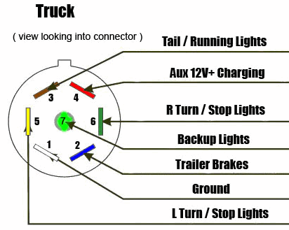
7 Way Diagram Aj S Truck Trailer Center from www.ajtnt.com This diagram shows the colors of a basic trailer wiring setup as well as what each wire is supposed to be connected to. Literally, a circuit is the path that enables electrical power to circulation. As a professional rv transporter i have seen to many trucks wired with those 2 wires to small and cause a fire from overheating. If your vehicle is not equipped with a working trailer wiring harness, there are a number of different solutions to provide the perfect fit for. 4 pin trailer light wiring diagram : Of course the more items you have the more poles you will need on your connector. 7 way plug wiring diagram standard wiring* post purpose wire color tm park light green (+) battery feed black rt right turn/brake light brown lt left turn/brake light red s trailer electric brakes blue gd ground white a accessory yellow this is the most common (standard) wiring scheme for rv plugs and the one used by major auto manufacturers today. Enclosed trailer 110v wiring diagram obviously, i could haul the trailer to my rv shop and let them handle everything but i feel relatively comfortable around wiring and this site is.
This diagram shows the colors of a basic trailer wiring setup as well as what each wire is supposed to be connected to.
A wiring diagram is a simplified conventional photographic depiction of an electric circuit. Above we have describes the main types of trailer wiring diagrams. As a professional rv transporter i have seen to many trucks wired with those 2 wires to small and cause a fire from overheating. When shopping for trailer connectors remember that the male end is mounted on the vehicle side and the female on the trailer side. The diagrams below show the typical trailer wiring for 4 pin flat connectors all the way to 7 pin round connectors. 4 way flat molded connectors allow basic hookup for three lighting functions; Literally, a circuit is the path that enables electrical power to circulation. 7 way plug wiring diagram standard wiring* post purpose wire color tm park light green (+) battery feed black rt right turn/brake light brown lt left turn/brake light red s trailer electric brakes blue gd ground white a accessory yellow this is the most common (standard) wiring scheme for rv plugs and the one used by major auto manufacturers today. This automobile is designed not only to travel 1 location to another but also to take heavy loads. A lot of led lights come with black and white wires and people can easily confuse the black wire for the ground. The image above shows a single axle trailer, and the next image shows wiring for tandem axles. It will help to have an understanding of trailer light systems and we recommend reviewing trailer wiring diagrams before starting this project. Typical trailer wiring diagram and schematic these 2 wire diagrams fit the needs of most trailers.
Obtaining from factor a to point b. The trailer wiring diagrams listed below, should help identify any wiring issues you may have with your trailer. To wire a trailer, the first step is to determine what components on the trailer need wiring. The circuits are for left and right brake lights and running lights. Trailer plug wiring diagram to properly read a wiring diagram, one has to learn how typically the components in the system operate.
2008 Ford F550 Trailer Wiring Diagram Wiring Diagram Database Producer from ww2.justanswer.com Above we have describes the main types of trailer wiring diagrams. Only the (blue) brake and (white) ground wires are different. Below is the generic schematic of how the wiring goes. Trailer wiring diagrams trailer wiring connectors various connectors are available from four to seven pins that allow for the transfer of power for the lighting as well as auxiliary functions such as an electric trailer brake controller, backup lights, or a 12v power supply for a winch or interior To wire a trailer, the first step is to determine what components on the trailer need wiring. Typical trailer wiring diagram and schematic these 2 wire diagrams fit the needs of most trailers. The ground wire should be run from the frame of the. Variety of trailer breakaway wiring schematic.
The image above shows a single axle trailer, and the next image shows wiring for tandem axles.
Trailer wiring diagrams 4 way systems. Enclosed trailer 110v wiring diagram obviously, i could haul the trailer to my rv shop and let them handle everything but i feel relatively comfortable around wiring and this site is. When shopping for trailer connectors remember that the male end is mounted on the vehicle side and the female on the trailer side. Below is the generic schematic of how the wiring goes. Typical trailer wiring diagram and schematic these 2 wire diagrams fit the needs of most trailers. As a professional rv transporter i have seen to many trucks wired with those 2 wires to small and cause a fire from overheating. Right turn signal / stop light (green), left turn signal / stop light (yellow), taillight / license / side marker (brown) and a ground (white). Trailer wiring diagrams trailer wiring connectors various connectors are available from four to seven pins that allow for the transfer of power for the lighting as well as auxiliary functions such as an electric trailer brake controller, backup lights, or a 12v power supply for a winch or interior I am converting a 7x cargo trailer to a camper and want to wire it for 20a circuits, 10gauge service coming in wired for 30a main v. Only the (blue) brake and (white) ground wires are different. Literally, a circuit is the path that enables electrical power to circulation. The trailer wiring diagrams listed below, should help identify any wiring issues you may have with your trailer. It is important to note that the white wire is the ground wire, you will notice this even when you buy lights.
7 way plug wiring diagram standard wiring* post purpose wire color tm park light green (+) battery feed black rt right turn/brake light brown lt left turn/brake light red s trailer electric brakes blue gd ground white a accessory yellow this is the most common (standard) wiring scheme for rv plugs and the one used by major auto manufacturers today. When shopping for trailer connectors remember that the male end is mounted on the vehicle side and the female on the trailer side. A wiring diagram is a streamlined traditional photographic depiction of an electric circuit. Enclosed trailer 110v wiring diagram obviously, i could haul the trailer to my rv shop and let them handle everything but i feel relatively comfortable around wiring and this site is. A lot of led lights come with black and white wires and people can easily confuse the black wire for the ground.
Wiring Diagram Heritage Trailers from heritagetrailers.com Right turn signal / stop light (green), left turn signal / stop light (yellow), taillight / license / side marker (brown) and a ground (white). 7 way plug wiring diagram standard wiring* post purpose wire color tm park light green (+) battery feed black rt right turn/brake light brown lt left turn/brake light red s trailer electric brakes blue gd ground white a accessory yellow this is the most common (standard) wiring scheme for rv plugs and the one used by major auto manufacturers today. A wiring diagram is a streamlined traditional photographic depiction of an electric circuit. Collection of travel trailer wiring schematic. Here is a picture gallery about 6 wire trailer plug diagram complete with the description of the image, please find the image you need. The circuits are for left and right brake lights and running lights. Trailer wiring diagrams 4 way systems. Below is the generic schematic of how the wiring goes.
Yellow and green are for left and right turns and braking.
Above we have describes the main types of trailer wiring diagrams. Only the (blue) brake and (white) ground wires are different. For instance , when a module is usually powered up and it sends out a signal of fifty percent the voltage in addition to the technician will not know this, he would think he provides an issue, as he would expect a. It is important to note that the white wire is the ground wire, you will notice this even when you buy lights. You must check the trailer manual to see if the wiring is correct, but normally the white wire is called the ground wire, while the brown wire is used for tail lights. Yellow and green are for left and right turns and braking. The trailer wiring diagrams listed below, should help identify any wiring issues you may have with your trailer. Trailer wiring diagrams 4 way systems. Trailer wiring connectors various connectors are available from four to seven pins that allow for the transfer of power for the lighting as well as auxiliary functions such as an electric trailer brake controller, backup lights, or a 12v power supply for a winch or interior trailer lights. 4 pin trailer light wiring diagram : Here is a picture gallery about 6 wire trailer plug diagram complete with the description of the image, please find the image you need. A lot of led lights come with black and white wires and people can easily confuse the black wire for the ground. A simple closed system while it's never a good idea to dive into a wiring project blind, trailer wiring is actually very simple to work on and troubleshoot.