Home
› Consider The Juncion Of Three Wires As Shown In The Diagram. : Solved Consider The Junction Of Three Wires As Shown In T Chegg Com - The current in the circuit is 1 a.
Consider The Juncion Of Three Wires As Shown In The Diagram. : Solved Consider The Junction Of Three Wires As Shown In T Chegg Com - The current in the circuit is 1 a.
Consider The Juncion Of Three Wires As Shown In The Diagram. : Solved Consider The Junction Of Three Wires As Shown In T Chegg Com - The current in the circuit is 1 a.. The diagram shown in figure 4.2.2 (b) is called a flatband diagram. Conjectured rg flow diagrams for several different ranges. The open circles on the left side of the junction above represent holes or deficiencies of electrons in the lattice which can act like positive charge carriers. Find the magnitude and direction of the magnetic eld at point p due to the two 1.50 mm segments of wire that are opposite each other and 8.00 cm from point p. Express your answer in amperes to two significant figures.
Express your answer in amperes to two significant figures. Assume that i a current in a long wire produces magnetic field b at a distance d from the wire. The diagram shows some common circuit symbols. The diameter of wire 3 is 1.5 mm.express your answer in amperes per square millimeter to two significant figures. Current and current density at a junction consider the juncion of three wires as.
Solved A Review Constants Shown In The Diagram Consider T Chegg Com from media.cheggcdn.com Figure shows two long conducting wires placed at right angles. Electronics tutorial about junction field effect transistor also known as the jfet transistor used in amplifier and transistor switching circuits. A point at which two or more elements are joints together is called node.while a point where three or more in the above figure we can say that point a,b,c,d,e,f.are nodes and point c & f are called junction. Consider applying forward bias (voltage) v to junction. In the common source configuration (similar to common emitter), the input is applied to the gate and its output is taken from the drain as shown. Two parallel wires are 5.00 cm apart and carry currents in opposite directions, as shown in fig. Introduction to graduate studies in the college of business. When connected to fermi liquid reservoirs.
Two parallel wires are 5.00 cm apart and carry currents in opposite directions, as shown in fig.
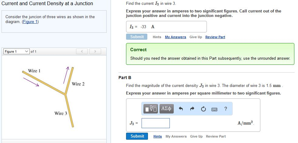
The tricky part of this question lies here: Consider a junction of five wires, as shown in the figure. Three identical point charges each of charge q are located at the vertices. The idea of a circuit diagram is to use circuit symbols instead of drawing each component in the circuit. This name refers to the horizontal band edges. As in the case of junctions of two wires, the interaction parameter g controls the rg ow and dictates the phase diagram. Assume that i a current in a long wire produces magnetic field b at a distance d from the wire. Consider a junction between p type and n type si. Wire current density amm2 diameter mm 1 31 16 2 49 28 find the current i3 in wire 3. Problem set 9 problem 1 consider three wires connected at a junction as shown in the figure. The magnitudes of the current density and the diameters for wires 1 and 2 are given in the table. Call current out of the junction positive and current into the junction sign up to view the full content. The overall pn junction should be electrically neutral since it is in equilibrium and.
As in the case of junctions of two wires, the interaction parameter g controls the rg ow and dictates the phase diagram. Current and current density at a junction consi. Thermodynamics, pv diagrams, internal energy, heat, work, isothermal, adiabatic, isobaric, physics. Two parallel wires are 5.00 cm apart and carry currents in opposite directions, as shown in fig. Express your answer in amperes to two significant figures.
Solved Consider The Juncion Of Three Wires As Shown In Th Chegg Com from d2vlcm61l7u1fs.cloudfront.net Consider a junction of five wires, as shown in the figure. A point at which two or more elements are joints together is called node.while a point where three or more in the above figure we can say that point a,b,c,d,e,f.are nodes and point c & f are called junction. The overall pn junction should be electrically neutral since it is in equilibrium and. Figure shows two long conducting wires placed at right angles. Consider the given information as length of stick is 9 ft. The diagram shown in figure 4.2.2 (b) is called a flatband diagram. The idea of a circuit diagram is to use circuit symbols instead of drawing each component in the circuit. Now we present our results for several dierent ranges of g.
The diameter of wire 3 is 1.5 mm.express your answer in amperes per square millimeter to two significant figures.
Consider a junction between p type and n type si. If d1 is 4 feet less than d2, what is d2, in feet? The two semiconductors are not recalling that electrostatic potentials need to be added to the energies in band diagrams, the equilibrium band diagram looks like as shown below. Fermi level of semiconductor is raised relative to that in metal current from semiconductor to metal so for capacitance (per unit area) c, can show. Hu_ch04v4.fm page 89 friday, february 13, 2009 5:54 pm pn and junctions chapter objectives this chapter introduces several devices that are formed (hist 1302) history of the united states (hist 106). Current and current density at a junction consi. Each ion channel, which is formed from a specialized protein. The current directions are indicated by the arrows. As shown in the diagram above, a diagram.jpg. The strength and direction of field at a point x marked in the figure will be. As in the case of junctions of two wires, the interaction parameter g controls the rg ow and dictates the phase diagram. The idea of a circuit diagram is to use circuit symbols instead of drawing each component in the circuit. Emitters unit 2facing one another across barrier.
Figure shows two long conducting wires placed at right angles. Consider, for example, the circuit illustrated in the figure below, consisting of five resistors in a kirchhoff's junction rule states that at any circuit junction, the sum of the currents flowing into and this is the second part of a system of three equations that we can use to find all three current values. The current directions are indicated by the arrows. I need help with part b. The current in the circuit is 1 a.
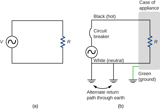
Household Wiring And Electrical Safety University Physics Volume 2 from opentextbc.ca The band diagrams of the two semiconductors, where apart, are shown in gure 2. As shown in the diagram above, a diagram.jpg. Call current out of the junction positive and current into the junction negative. The diagram shown in figure 4.2.2 (b) is called a flatband diagram. Emitters unit 2facing one another across barrier. In the common source configuration (similar to common emitter), the input is applied to the gate and its output is taken from the drain as shown. Consider three point charges located at the corners of a right triangle as shown in figure, where q1=q3=5.0 μc, q2=2.0 μc a uniformly charged insulating rod of length 14.0 cm is bent into the shape of a semicircle as shown in figure. Hu_ch04v4.fm page 89 friday, february 13, 2009 5:54 pm pn and junctions chapter objectives this chapter introduces several devices that are formed (hist 1302) history of the united states (hist 106).
Call current out of the junction positive and current into the junction negative.
Call current out of the junction positive and current into the junction negative. Now we present our results for several dierent ranges of g. Conjectured rg flow diagrams for several different ranges. This name refers to the horizontal band edges. The current directions are indicated by the arrows. I need help with part b. Two parallel wires are 5.00 cm apart and carry currents in opposite directions, as shown in fig. The magnitudes of the current density and the diameters for wires 1 and 2 are given in the table. As shown in the diagram above, a diagram.jpg. Geometry q&a library as shown in the diagram of rectangle abcd below, diagonals ac and bd intersect at e. The diameter of wire 3 is 1.5 mm.express your answer in amperes per square millimeter to two significant figures. Can effectively consider junction as 2 thermionic. Wire current density(a/mm2) diameter(mm) 1 3.0 2.0 2 5.0 3.0 find the current i3 in wire 3.