Home
› Electrical Diagram Symbols / Electronic Circuit Diagram Symbols Barrons Dictionary Allbusiness Com - Whether it is a complex control system on a machine tool or.
Electrical Diagram Symbols / Electronic Circuit Diagram Symbols Barrons Dictionary Allbusiness Com - Whether it is a complex control system on a machine tool or.
Electrical Diagram Symbols / Electronic Circuit Diagram Symbols Barrons Dictionary Allbusiness Com - Whether it is a complex control system on a machine tool or.. The symbols in figure 8 are used to identify the larger components that may be found in an electrical diagram or schematic. The wiring diagram is used for the representation of electrical components in their approximate physical location using their specific symbols and their interconnections using lines. However, today most of the symbols are internationally standardized. Basics 10 480 v pump schematic : Whether it is a complex control system on a machine tool or.
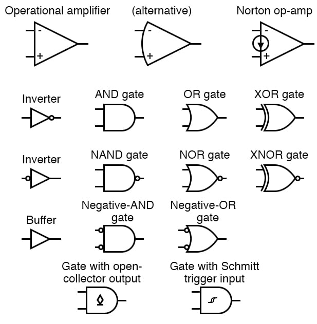
Iec schematic diagrams general with the increasing emphasis on globalization, many industries are now looking to all parts of the. Basics 13 valve limit switch legend : Amplifiers (denoted by triangle shapes) increase the output signal in your circuit. Among these you'll find commonly used electrical drawings and schematics, like circuit diagrams, wiring diagrams, electrical plans and block diagrams. The detail used for these symbols will vary when used in system diagrams.
12 Volt Relay Wiring Diagram Symbols Wiringdiagram Org Electrical Symbols Electrical Wiring Diagram Electrical Diagram from i.pinimg.com Since the electrical standards adopted by various nations may vary, the markings and symbols used to describe electrical control products vary as well. Basics 10 480 v pump schematic : Templates, tools & symbols for electrical, wiring, circuit & other schematics. We walk through some of the basics and most common symbols associated with reading an air conditioner wiring schematic or diagram.read all the tech tips, tak. Usually the amount of detail will reflect the relative importance of a component to the particular diagram. Vertical and horizontal lines are used to represent wires and each line represents a single wire that connects between electrical components. The symbols represent electrical and electronic components. The symbols listed in this handbook were collected after much research by the technical staff of cleveland institute of electronics, inc.
The schematics symbols for most major electrical components can be found in this table.
Basics 8 aov elementary & block diagram : This article gives some of the frequently used symbols for drawing the circuits. Basics 13 valve limit switch legend : Whether it is a complex control system on a machine tool or. Contacts time delay after coil normally open normally closed normally open normally closed relay, etc. Amplifiers (denoted by triangle shapes) increase the output signal in your circuit. Usually the amount of detail will reflect the relative importance of a component to the particular diagram. The symbols in figure 8 are used to identify the larger components that may be found in an electrical diagram or schematic. It makes the graphical representation easier to work on and implement. (cont.) ground chassis or frame not necessarily grounded plug and recp. Basic electrical symbols contain earth electrode, cell, battery, resistor, etc. However, each component may have numerous possible representations. Templates, tools & symbols for electrical, wiring, circuit & other schematics.
There are some standard symbols to represent the components in a circuits. (cont.) ground chassis or frame not necessarily grounded plug and recp. Electrical symbols or electronic circuits are virtually represented by circuit diagrams. Capacitors (parallel lines) store energy in your system, while resistors (zigzag lines) reduce current flow. Basics 13 valve limit switch legend :
Integrated Circuits Circuit Schematic Symbols Electronics Textbook from www.allaboutcircuits.com In cases where there is more than one common symbol we have tried to give an alternate representation. Electrical symbols or electronic circuits are virtually represented by circuit diagrams. Here is a standard wiring symbol legend featuring detailed documentation of wiring diagrams, home wiring plans, and common symbols used in electrical wiring blueprints. The symbols in figure 8 are used to identify the larger components that may be found in an electrical diagram or schematic. Since the electrical standards adopted by various nations may vary, the markings and symbols used to describe electrical control products vary as well. Contacts time delay after coil normally open normally closed normally open normally closed relay, etc. The wiring diagram is used for the representation of electrical components in their approximate physical location using their specific symbols and their interconnections using lines. Basics 13 valve limit switch legend :
Basics 13 valve limit switch legend :
You can depict a complex electrical circuit with the standard and simplified electrical symbols. The symbols listed in this handbook were collected after much research by the technical staff of cleveland institute of electronics, inc. Electrical symbols are used to represent electrical and electronic devices in schematic diagrams. The symbols in figure 8 are used to identify the larger components that may be found in an electrical diagram or schematic. Electrical symbols and electronic circuit symbols are used for drawing schematic diagram. Conceptdraw diagram diagramming and vector drawing software supplied with unique electrical engineering solution from the industrial engineering area will help you design electrical diagram of any complexity without efforts. There are some standard symbols to represent the components in a circuits. Contacts time delay after coil normally open normally closed normally open normally closed relay, etc. The detail used for these symbols will vary when used in system diagrams. Electrical symbols are the most commonly used symbols in circuit diagramming. The most commonly used electrical blueprint symbols including plug outlets, switches, lights and other special symbols such as door bells and smoke detectors are shown in the figure below. (cont.) ground chassis or frame not necessarily grounded plug and recp. Electrical symbols and line diagrams chapter 3 material taken from chapter 3 of electric motor controls, g.
The symbols in figure 8 are used to identify the larger components that may be found in an electrical diagram or schematic. You can tell by the symbols that this single line diagram has three resistors and a battery. Electrical symbols or electronic circuits are virtually represented by circuit diagrams. Since the electrical standards adopted by various nations may vary, the markings and symbols used to describe electrical control products vary as well. Basics 14 aov schematic (with block included)
Lessons In Electric Circuits Volume V Reference Chapter 9 from techwritingcareer.com Note the coloring used to illustrate circuit breaker states (green = off and red. The wiring diagram is used for the representation of electrical components in their approximate physical location using their specific symbols and their interconnections using lines. The schematics symbols for most major electrical components can be found in this table. Amplifiers (denoted by triangle shapes) increase the output signal in your circuit. However, each component may have numerous possible representations. Electrical diagram is a visual graphical representation of an electrical circuit. Basics 14 aov schematic (with block included) Electrical symbols or electronic circuits are virtually represented by circuit diagrams.
Basic electrical symbols contain earth electrode, cell, battery, resistor, etc.
Basic electrical symbols contain earth electrode, cell, battery, resistor, etc. Whether you are a novice or a professional engineer, these basic symbols can help create accurate electrical and circuit diagrams in minutes. Conceptdraw diagram diagramming and vector drawing software supplied with unique electrical engineering solution from the industrial engineering area will help you design electrical diagram of any complexity without efforts. Electrical diagram is a visual graphical representation of an electrical circuit. Note the coloring used to illustrate circuit breaker states (green = off and red. This article gives some of the frequently used symbols for drawing the circuits. (cont.) ground chassis or frame not necessarily grounded plug and recp. The electrical symbols represent various components, devices, and functionalities present in a circuit. The symbols listed in this handbook were collected after much research by the technical staff of cleveland institute of electronics, inc. Among these you'll find commonly used electrical drawings and schematics, like circuit diagrams, wiring diagrams, electrical plans and block diagrams. Usually the amount of detail will reflect the relative importance of a component to the particular diagram. Amplifiers (denoted by triangle shapes) increase the output signal in your circuit. There are some standard symbols to represent the components in a circuits.