Home
› 4 Wire Stepper Motor Wiring Diagram : Https Encrypted Tbn0 Gstatic Com Images Q Tbn And9gcsd0k7qczcqagalaydcy Lqjsdad4vwywvmhj2hxogzm5ukqjfp Usqp Cau / About all reprap stepper drivers are bipolar (as opposed to unipolar), so if you're using the standard drivers, you will need a stepper than can be wired as bipolar.
4 Wire Stepper Motor Wiring Diagram : Https Encrypted Tbn0 Gstatic Com Images Q Tbn And9gcsd0k7qczcqagalaydcy Lqjsdad4vwywvmhj2hxogzm5ukqjfp Usqp Cau / About all reprap stepper drivers are bipolar (as opposed to unipolar), so if you're using the standard drivers, you will need a stepper than can be wired as bipolar.
4 Wire Stepper Motor Wiring Diagram : Https Encrypted Tbn0 Gstatic Com Images Q Tbn And9gcsd0k7qczcqagalaydcy Lqjsdad4vwywvmhj2hxogzm5ukqjfp Usqp Cau / About all reprap stepper drivers are bipolar (as opposed to unipolar), so if you're using the standard drivers, you will need a stepper than can be wired as bipolar.. This type of motor is more complex to use, but with tester and some patience you can find the 4 wires you need to connect. So when you search the web, you will find these diagrams with north. Or perhaps a wiring diagram for such a stepper. You can distinguish them from unipolar steppers by measuring the resistance between the wires. To understand this we should first know.
It is an incremental drive (digital) actuator and is driven in fixed angular steps. Architectural wiring diagrams play a role the approximate locations and interconnections of receptacles, lighting, and permanent electrical services in a building. 4 wire motor wiring diagram | wirings diagram as stated earlier, the lines at a 4 wire motor wiring diagram signifies wires. Connect the stepper motor to the arduino by following the wiring diagram. Unlike unipolar steppers, bipolar steppers have no common center connection.
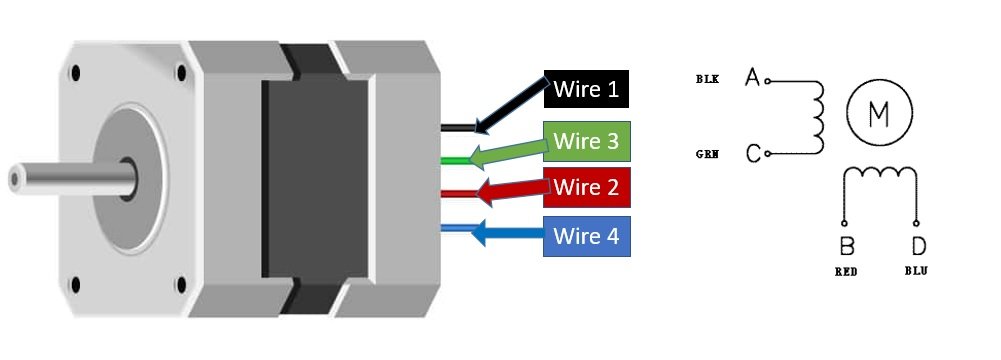
Stepper Motors Code Circuits Construction from tigoe.com i do not respond to personal messages, i will delete them unread, use the forum please . At times, the cables will cross. Effectively read a electrical wiring diagram, one provides to find out how the particular components inside the system operate. Stepper motors are increasingly taking its position in the world of the electronics. The bipolar stepper motor usually has four wires coming out of it. To understand this we should first know. They have two independent sets of coils instead. The motor has six wires, connected to two split windings as is common for unipolar stepper motors.
Connecting a stepper motor to a buildbotics cnc controller requires properly connecting the four wires from the driver to the right wires on the motor.
Since coils a and b on the diagram above are not connected, the resistance between leads a1 and b1, or between a1 and b2 will be infinite. Controls a 4 wire stepper motor. What causes resolution in the stepper motor is the number of phases with the number of teeth. Follow the wiring diagram with each stepper motor. To understand this we should first know. So when you search the web, you will find these diagrams with north. The standard stepper motors offered by thomson come in a four wire, bipolar configuration, as illustrated in figure 2 and table 2. 200 steps per revolution, 1.8 degrees. Architectural wiring diagrams play a role the approximate locations and interconnections of receptacles, lighting, and permanent electrical services in a building. You can distinguish them from unipolar steppers by measuring the resistance between the wires. The wiring diagram/schematic above shows you how to connect the a4899 driver to a stepper motor and the arduino. Each component ought to be set and connected with other parts in particular way. Starting from a normal surveillance camera to a complicated cnc okay, so unlike a normal dc motor this one has five wires of all fancy colors coming out of it and why is it so?
Unfortunately, stepper motors come in a variety of configurations and it is not always immediately obvious how to hook them up. The bipolar stepper motor usually has four wires coming out of it. Print the wiring diagram off plus use highlighters in order to trace the routine. Route high‐voltage power cables separately segregate input power wiring and stepper motor power cables from control wiring and motor it is very important that the wiring of the stepper motor and driver be taken into consideration upon. You will need a hardware driver connected between arduino and the motor.
Nema 23 Stepper Motor Pinout Features And Example With Arduino from microcontrollerslab.com Effectively read a electrical wiring diagram, one provides to find out how the particular components inside the system operate. Some of these newer motors had different current requirements, wiring, and shaft sizes than their older counterparts. Use this component to control a 4 wire stepper motor. Please note that you should never connect a motor physically directly to an arduino board, unless the board has built in motor drivers. For induction motors and reversible motors this diagram will help you wire your motor (four pins) these are the motor connections. 4 wire stepper motor has 2 leads in each phase, h bridges with some driving topologies do have static friction effects, but this effect can be reduced by dithering stepper motor signals at higher frequencies. Stepper motors are increasingly taking its position in the world of the electronics.
Architectural wiring diagrams play a role the approximate locations and interconnections of receptacles, lighting, and permanent electrical services in a building.
Starting from a normal surveillance camera to a complicated cnc okay, so unlike a normal dc motor this one has five wires of all fancy colors coming out of it and why is it so? The motor has six wires, connected to two split windings as is common for unipolar stepper motors. The wiring diagram/schematic above shows you how to connect the a4899 driver to a stepper motor and the arduino. Black, yellow, green wires is part of first winding where black. I bought second hand a 4 wire. Or perhaps a wiring diagram for such a stepper. Connecting to the stepper motor will require a. Stepper motor wiring diagram from knowledge.ni.com. For induction motors and reversible motors this diagram will help you wire your motor Each component ought to be set and connected with other parts in particular way. Easy identify leads on a 4 wire stepper motor with multimeterstepper motors comes with different winding configurations. Use this component to control a 4 wire stepper motor. Unfortunately, stepper motors come in a variety of configurations and it is not always immediately obvious how to hook them up.
Stepper motors are increasingly taking its position in the world of the electronics. This creates an extra wire for each on duet 2 maestro and duet 3, the four motor connector pins are labelled 'b1 b2 a1 a2' on the back of the board and on the wiring diagram. Or perhaps a wiring diagram for such a stepper. For example , if a module will be powered up and it also sends out a signal of 50 percent the voltage and the technician. The standard stepper motors offered by thomson come in a four wire, bipolar configuration, as illustrated in figure 2 and table 2.
Identify Leads On A 8 Wire Stepper Motor Victor Leung from www.dreamationworks.com Print the wiring diagram off plus use highlighters in order to trace the routine. Or perhaps a wiring diagram for such a stepper. Difference between 4 wire 6 wire and 8 wire stepper motors. You can distinguish them from unipolar steppers by measuring the resistance between the wires. In an effort to constantly improve our products, amci has replaced older versions of our stepper motors with new, more powerful motors. Wiring diagram will come with several easy to adhere to wiring diagram instructions. The only thing you need to identify is the two pairs of wires which are. Stepper motors are increasingly taking its position in the world of the electronics.
They have two independent sets of coils instead.
I want to wire two stepper motors together so one is hand cranked, an alternator, that drives the second stepper motor. You will need a hardware driver connected between arduino and the motor. Wiring diagram will come with several easy to adhere to wiring diagram instructions. The connections are also given i use the following trick to determine how to connect 4 wire bipolar stepper motors: Difference between 4 wire 6 wire and 8 wire stepper motors. Effectively read a electrical wiring diagram, one provides to find out how the particular components inside the system operate. On arduino website, the sample circuit's stepper has 4 wires and is directly connected to a driver ic (a lmxxx), and the. Connecting to the stepper motor will require a. Controls a 4 wire stepper motor. If your stepper motor has 4 wires, it is a bipolar stepper motor. Unfortunately, stepper motors come in a variety of configurations and it is not always immediately obvious how to hook them up. Black, yellow, green wires is part of first winding where black. How to use an arduino stepper motor in ozeki.