Xor Ladder Logic Diagram : 5 Ladder Logic Dr Stienecker S Site - 2006 dodge charger srt8 fuse diagram?. Ladder diagrams are specialized schematics commonly used to document industrial control logic systems. That is, a true output results if one, and only one, of the inputs to the gate is true. The programming methods can be with logic ladder diagram, mneumonic (statement list), and / or function block diagram. Ladder diagrams describe programs in graphical form, used in plc programming. It is one of the languages that the iec 61131 standard specifies for use with plcs.
Each device in the relay rack would be represented by a symbol on the ladder diagram with connections between those devices shown. A logic gate is a device that can perform one or all of the boolean logic operations and, nand, nor, not, or, xnor, and xor. A ladder diagram is the symbolic representation of the control logic used for ladder logic programming of a plc. There are some methods to do plc programming. Ladder logic uses switch or relay contacts to implement in the case of ladder logic, logic functions are implemented by developing a ladder diagram.
Plc Logic Functions Plc Ladder Logic Gates Plc Commands from instrumentationtools.com There are some methods to do plc programming. Now, you may have noticed in the ladder logic diagram example above, there are multiple inputs in the same rung. Ladder diagrams describe programs in graphical form, used in plc programming. The logic diagram consists of gates and symbols that can directly replace an expression in boolean arithmetic. This diagram is developed from structured relay contacts that describe the flow of electric current. The ladder logic implementation of xor gate is shown in below figure: Basically, there are seven types of logic gates as below. Read about ladder diagrams (ladder logic) in our free electronics textbook.
Ladder logic is the basis of most control functions.
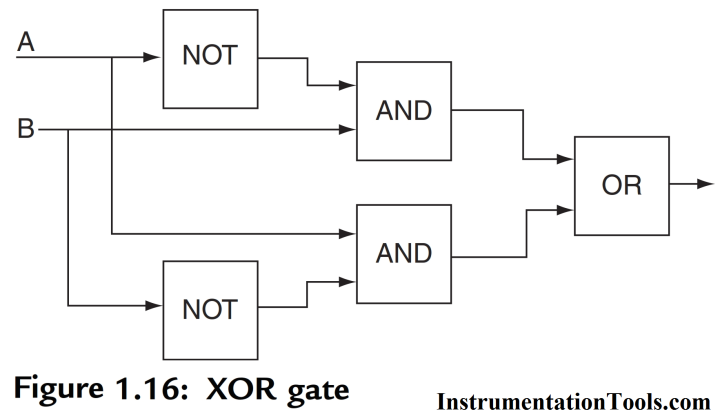
Any instruction that can replace a contact. The ladder logic implementation of xor gate is shown in below figure: One of the plc programming methods that are very commonly used programming using plc ladder diagram. Plc ladder programming plc is a logic controller which has inputs and outputs to control a particular process. Each device in the relay rack would be represented by a symbol on the ladder diagram with connections between those devices shown. Ladder logic uses switch or relay contacts to implement in the case of ladder logic, logic functions are implemented by developing a ladder diagram. When the voltage at a and b terminals are at opposite logic state, a voltage of. Ladder logic diagram xor is affable in our digital library an online access to it is set as public so you can download it instantly. They are called ladder diagrams because they resemble a ladder, with two vertical rails (supply power) and as many rungs (horizontal lines) as there are control circuits to represent. The ladder diagram starts with j j, normally open contacts labeled input a, to represent switch a and in parallel with it j j, normally open contacts one way of obtaining such a gate is by using not, and and or gates as shown in figure 1.16. Now it has gone a little complex but lets understand how's its working. In the case of both switches (i1 and i2) are. They are called ladder diagrams because they resemble a ladder, with two vertical rails (supply power) and.
In the ladder diagram there are two vertical lines where the left vertical line is connected to the positive voltage. Ladder logic is made out of rungs of logic, forming what. The ladder logic implementation of xor gate is shown in below figure: An xor gate implements an exclusive or; Read about ladder diagrams (ladder logic) in our free electronics textbook.
Plc Lab Exercise Logic Gates Plc Ladder Logic Diagram Examples from i2.wp.com The ladder diagram starts with j j, normally open contacts labeled input a, to represent switch a and in parallel with it j j, normally open contacts one way of obtaining such a gate is by using not, and and or gates as shown in figure 1.16. Our digital library saves in multipart countries, allowing you to acquire the most less latency time to download any of our books considering this one. B ' so the conversion to ladder diagram, logic xor similarly, the logic of the previous ones. 1987 suzuki samurai fuse box diagram. Each device in the relay rack would be represented by a symbol on the ladder diagram with connections between those devices shown. It is a graphical plc programming language which expresses logic operations with symbolic notation. There are some methods to do plc programming. 2006 dodge charger srt8 fuse diagram?
Different types of ladder logic diagram that perform different logic gate functions.
They are called ladder diagrams because they resemble a ladder, with two vertical rails (supply power) and as many rungs (horizontal lines) as there are control circuits to represent. There are many control situations requiring actions to be initiated when a certain combination of conditions is realized. Basically, there are seven types of logic gates as below. Ladder diagrams have horizontal lines of control logic called rungs and vertical lines at the start and end of each rung called rails. An xor implementation for two inputs, which is actually [(a and b') or (a' and b). 01 wrangler engine wiring diagram. This diagram is developed from structured relay contacts that describe the flow of electric current. 1987 suzuki samurai fuse box diagram. Ladder logic is the basis of most control functions. Ladder logic is pretty well the universal programming language of plcs. Now it has gone a little complex but lets understand how's its working. There are some methods to do plc programming. In the case of both switches (i1 and i2) are.
One of the plc programming methods that are very commonly used programming using plc ladder diagram. They are called, respectively, the rails and the rungs. O = (a + b) '= a'. When input a and input b are not activated then there is 0 output. Plc ladder programming plc is a logic controller which has inputs and outputs to control a particular process.
Logical Gates In Ladder Logic For Plc The Engineering Projects from www.theengineeringprojects.com Basically, there are seven types of logic gates as below. Xor gate (sometimes eor, or exor and pronounced as exclusive or) is a digital logic gate that gives a true (1 or high) output when the number of true inputs is odd. 1987 suzuki samurai fuse box diagram. Diagram xor ladder logic diagram xor 9 out of 10 based on 70 ratings. Ladder logic diagram xor is affable in our digital library an online access to it is set as public so you can download it instantly. Ladder diagrams have horizontal lines of control logic called rungs and vertical lines at the start and end of each rung called rails. The ladder logic implementation of xor gate is shown in below figure: Ladder logic uses switch or relay contacts to implement in the case of ladder logic, logic functions are implemented by developing a ladder diagram.
When the voltage at a and b terminals are at opposite logic state, a voltage of.
Ladder diagrams are to be thought of as virtual circuits, where virtual power flows through virtual contacts (when closed) to energize virtual relay coils to perform logical functions. The programming methods can be with logic ladder diagram, mneumonic (statement list), and / or function block diagram. The output of the xor gate is low for similar inputs while for the dissimilar inputs the output is high. 2006 dodge charger srt8 fuse diagram? The ladder logic diagram consists of two fundamental parts, which you can see as the vertical and the horizontal lines. Read about ladder diagrams (ladder logic) in our free electronics textbook. They are called ladder diagrams because they resemble a ladder, with two vertical rails (supply power) and as many rungs (horizontal lines) as there are control circuits to represent. For this program, the relay logic's ladder diagram is duplicated with ladder logic; Ladder diagrams have horizontal lines of control logic called rungs and vertical lines at the start and end of each rung called rails. Different types of ladder logic diagram that perform different logic gate functions. An xor gate implements an exclusive or; Engr fahad — august 23, 2019 add comment. Ladder logic was designed to have the same look and feel as electrical ladder diagrams, but with ladder logic, the physical contacts and coils are replaced with memory bits.