Home
› Mobile Jammer Circuit Diagram Pcb Layout / Gbppr 800 Mhz Cellular Phone Jammer : This cell phone signal jammer circuit using 555 timer will effectively jam all types of mobile band signals.
Mobile Jammer Circuit Diagram Pcb Layout / Gbppr 800 Mhz Cellular Phone Jammer : This cell phone signal jammer circuit using 555 timer will effectively jam all types of mobile band signals.
Mobile Jammer Circuit Diagram Pcb Layout / Gbppr 800 Mhz Cellular Phone Jammer : This cell phone signal jammer circuit using 555 timer will effectively jam all types of mobile band signals.. Cellular phone jammer rf amplifier circuit diagram. The lna evaluation board of the bgu8009 can , receiver implemented in a mobile phone requires the following factors to be taken into account. Egg timer circuit diagram, pcb layout and assembly information. Cell jammer schematic you can try this out. The jamming circuit broadcasts an rf signal in the frequency range reserved for cell phones that interferes with the cell phones popular as mobile phones are the ones we cannot separate from the essential list.
For any jammer circuit, there are 5 main important circuits. Htc desire 728g pcb layout of mobile jammer circuit. Mobile pcb diagram free download helps you identify mobile phone circuit board original parts and components. Diy cellphone jammers & blocker electronic schematic circuit diagram with working but usually most of the mobile phones operate at a band between 800mhz to 950 mhz. After building this circuit on a perf board and supplying power to it, i have placed a mobile phone near the circuit (i am yet to turn on the switch).
How To Make A Powerful Rf Signal Jammer Circuit Homemade Circuit Projects from homemade-circuits.com Mobile jammer report printed circuit board rectifier. Figure 1 shows the block diagram for the jammer to be designed. Cell phone jammer circuit engineering projects. By now, they have become an inseparable part of our lives. Simple mobile jammer circuit _how cell phone jammer works. I like to share the knowledge. Sale frequency jammer circuit diagram mobile phone search which mobile phone mobile phone comparison cheap mobile phones circuit diagram of block diagram cell phone jammer phone jammers what is the best mobile phone sell my mobile mobile phones mobile phone sales mobile. A wonderful diy gsm jammer otherwise cellular mobile phone jammer schematic diagram instead of application single taking part in gsm1900 with frequency from 1930 mhz to 1990 mhz.
Egg timer circuit diagram, pcb layout and assembly information.
Pcb layout is an essential part of an rf circuit design. Portable pcs cellular phone jammer circuit schematic. Egg timer circuit diagram, pcb layout and assembly information. All mobile phone circuit board diagram mobile phone pcb diagram. Cellphone jammer circuit using high frequency rf transistors. How to make cell phone signal jammer electronics projects hub. Figure 1 shows the block diagram for the jammer to be designed. Mobile pcb diagram free download helps you identify mobile phone circuit board original parts and components. The lna evaluation board of the bgu8009 can , receiver implemented in a mobile phone requires the following factors to be taken into account. Jamming techniques 143.2 mobile jamming requirements 18chapter 4 hardware 2013 page 31chapter 4hardware implementation4.1 circuit diagramcircuit diagram involves rectifier, pic microcontroller. 4.3 schematic, pcb layout, and implementation. Inverter pcb layout design inverter circuit and products. After building this circuit on a perf board and supplying power to it, i have placed a mobile phone near the circuit (i am yet to turn on the switch).
No abstract text available text: Cell jammer schematic you can try this out. Download the pcb files and cell phone signal jammer circuit diagram. When learning how to read all mobile pcb diagrams, step one is to identification of external parts on the mobile phone. Figure 1 shows the block diagram for the jammer to be designed.
Index Of Wp Content Uploads 2016 03 from bestengineeringprojects.com This is the most important part of the jammer, since the output of this section will be interfacing with the mobile. Tv remote control jammer circuit using 555 timer ic. This cell phone signal jammer circuit using 555 timer will effectively jam all types of mobile band signals. Cell phone jammer is an electronic device that blocks transmission of signals between a cell phone and a base station. Portable pcs cellular phone jammer circuit schematic. Breadboards are great for prototyping circuits, but they aren't so good for actually using the thing before you start designing your pcb, it's a good idea to make a schematic of your circuit. The jamming circuit broadcasts an rf signal in the frequency range reserved for cell phones that interferes with the cell phones popular as mobile phones are the ones we cannot separate from the essential list. Simple mobile jammer circuit |how cell phone jammer works?
Get complete knowledge on mobile phone jammer circuit and its working.
Get more information about mobile jammer circuit diagram pcb layout by visiting this link. So can anyone suggest a better circuit diagram for mobile jammer or signal signal jammer circuit. Mobile phone detector hobby project circuit diagram. Mobile jammer report printed circuit board rectifier. Edaboard.com is an international electronic discussion forum focused on eda software, circuits, schematics, books, theory, papers, asic, pld, 8051, dsp, network, rf, analog design, pcb, service manuals. And a whole lot more! Acer mobile phone circuit diagram pdf. When learning how to read all mobile pcb diagrams, step one is to identification of external parts on the mobile phone. All mobile phone circuit board diagram mobile phone pcb diagram. In this pcb layout tutorial i hope to tell you how to create a good pcb layout very easily and clearly. The jamming circuit broadcasts an rf signal in the frequency range reserved for cell phones that interferes with the cell phones popular as mobile phones are the ones we cannot separate from the essential list. Tv remote control jammer circuit using 555 timer ic. If you understand the above circuit, this circuit analysis is simple and.
Tv remote control jammer circuit using 555 timer ic. Inverter pcb layout design inverter circuit and products. Pcb layout is an essential part of an rf circuit design. I like to share the knowledge. With capacitor 1 set at roughly.
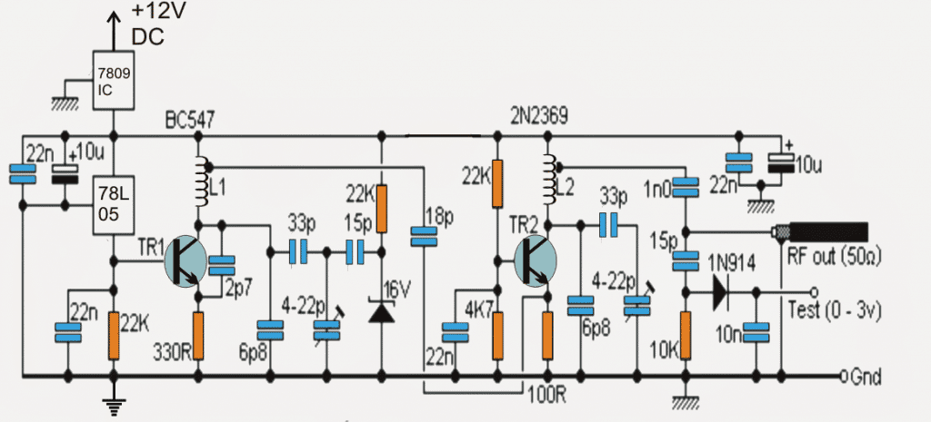
Mobile Phone Jammer Circuit Diagram What Is Mobile Cell Phone Jammer from circuitspedia.com Sale frequency jammer circuit diagram mobile phone search which mobile phone mobile phone comparison cheap mobile phones circuit diagram of block diagram cell phone jammer phone jammers what is the best mobile phone sell my mobile mobile phones mobile phone sales mobile. Download the pcb files and cell phone signal jammer circuit diagram. In this pcb layout tutorial i hope to tell you how to create a good pcb layout very easily and clearly. Diy mobile phone jammer circuit schematic. I like to share the knowledge. Htc mobile phone parts and functions pdf. Get complete knowledge on mobile phone jammer circuit and its working. Cellphone jammer circuit using high frequency rf transistors.
4.3 schematic, pcb layout, and implementation.
Mobile pcb diagram free download helps you identify mobile phone circuit board original parts and components. Egg timer circuit diagram, pcb layout and assembly information. Diy mobile phone jammer circuit schematic. When learning how to read all mobile pcb diagrams, step one is to identification of external parts on the mobile phone. Portable pcs cellular phone jammer circuit schematic. With capacitor 1 set at roughly. Get complete knowledge on mobile phone jammer circuit and its working. In this pcb layout tutorial i hope to tell you how to create a good pcb layout very easily and clearly. Cell jammer schematic you can try this out. A wonderful diy gsm jammer otherwise cellular mobile phone jammer schematic diagram instead of application single taking part in gsm1900 with frequency from 1930 mhz to 1990 mhz. Tv remote control jammer circuit using 555 timer ic. Pcb of rf section of the mobile jammer. This is the most important part of the jammer, since the output of this section will be interfacing with the mobile.