Home
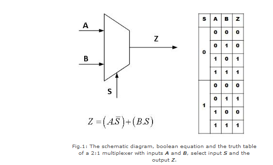
› 2X1 Mux Logic Diagram / Implementation Of 4x1 Mux Using 2x1 Mux ह न द Youtube - Output follows one of the inputs depending upon the state of the select lines.
2X1 Mux Logic Diagram / Implementation Of 4x1 Mux Using 2x1 Mux ह न द Youtube - Output follows one of the inputs depending upon the state of the select lines.
2X1 Mux Logic Diagram / Implementation Of 4x1 Mux Using 2x1 Mux ह न द Youtube - Output follows one of the inputs depending upon the state of the select lines.. 1 mux selects either a or b depending upon the control. The block diagram of mux with n data sources of b bits wide and s bits wide select line is shown in below figure. The logic for the complete multiplexer is shown in figure 3 where the two mux4_cells are combined together with figure 3: How to make 8x1 multiplexer using 2 4x1 multiplexer? Implement a full adder with two 4 x 1 multiplexers.
Now, to implement this 8x1 mux using 4x1 mux we need two 4x1 mux, since to take 8 inputs atleast two 4x1 mux required, 4 inputs on each of the muxes having selection lines s1 & s0. Let us assume logical area of a 2:1 mux to be a. The implementation of not gate is done using n selection lines. Multiplexers, or mux's, can be either digital circuits made from high speed logic gates used to switch digital or binary data or they can be analogue types using transistors 4 channel multiplexer using logic gates. Spelled sometimes as multiplexor), also known as a data selector, is a device that selects between several analog or digital input signals and forwards the selected input to a single output line.
Virtual Lab from www.iitg.ac.in Multiplexer can act as universal combinational circuit. The selection is directed a separate set of digital inputs known as select lines. The block diagram of mux with n data sources of b bits wide and s bits wide select line is shown in below figure. A8da3 8 1 mux logic diagram digital resources. The block diagram of 4x1 multiplexer is shown in the following figure. How do implement an 8 1 line multiplexer using two 4 1. Firstly i will introduce what is mux. 1 mux selects either a or b depending upon the control.
1 multiplexer using transmission gates.
A multiplexer is also called a data selector. Multiplexers different ways to implement verilog by examples. In electronics, a multiplexer (or mux; The implementation of not gate is done using n selection lines. Table 1 the comparison of different techniques w.r.t area and power dissipation. 7 layout of 2t mux. A demultiplexer is a combinational logic circuit that receives information on a single line and transmits this information on one of 2 n possible output lines. The first level of a. The block diagram of mux with n data sources of b bits wide and s bits wide select line is shown in below figure. Figure 2(a) and i am also will tell about its working with logic diagram and uses. Truth table for 8 to 1 multiplexer. In this post, i will tell you what is multiplexer (mux) and i am also will tell you about its working with logic diagram and uses. Hello, can someone please explain me how to design a logic circuit of 4x1 mux using 2x1 muxes and logic gates ?
How do implement an 8 1 line multiplexer using two 4 1. The block diagram of mux with n data sources of b bits wide and s bits wide select line is shown in below figure. Output follows one of the inputs depending upon the state of the select lines. The operation of dynamic logic is based on storage of charge on capacitive node 6. Multiplexers, or mux's, can be either digital circuits made from high speed logic gates used to switch digital or binary data or they can be analogue types using transistors 4 channel multiplexer using logic gates.
2 X 1 Multiplexer Youtube from i.ytimg.com 2x1 mux vlsi n eda. Multiplexer (mux) 2 x 1mux design watch more videos at www.tutorialspoint.com/videotutorials/index.htm lecture by: The general block level diagram of a multiplexer is shown below. The block diagram of mux with n data sources of b bits wide and s bits wide select line is shown in below figure. Now, to implement this 8x1 mux using 4x1 mux we need two 4x1 mux, since to take 8 inputs atleast two 4x1 mux required, 4 inputs on each of the muxes having selection lines s1 & s0. The implementation of not gate is done using n selection lines. Tie the input logic of i(0) to 1 and i(1) to 0 and calculate the output on the basis of select line and mux truth table. The block diagram of 4x1 multiplexer is shown in the following figure.
Tie the input logic of i(0) to 1 and i(1) to 0 and calculate the output on the basis of select line and mux truth table.
Multiplexers, or mux's, can be either digital circuits made from high speed logic gates used to switch digital or binary data or they can be analogue types using transistors 4 channel multiplexer using logic gates. Spelled sometimes as multiplexor), also known as a data selector, is a device that selects between several analog or digital input signals and forwards the selected input to a single output line. Hello, can someone please explain me how to design a logic circuit of 4x1 mux using 2x1 muxes and logic gates ? 7 shows the layout diagram generated by tool. How do implement an 8 1 line multiplexer using two 4 1. Let us assume logical area of a 2:1 mux to be a. 2:1 mux verilog in data flow model is given below. Multiplexers different ways to implement verilog by examples. Vhdl code of 8x1mux using two 4x1 mux : It has 4 select lines and 16 inputs. Vlsi n eda the logic circuit and symbol of 2x1 mux is shown in figure 2. The remaining single variable of the function is used for the. The selection is directed a separate set of digital inputs known as select lines.
Multiplexers different ways to implement verilog by examples. 1 mux selects either a or b depending upon the control. Figure 2(a) and i am also will tell about its working with logic diagram and uses. A demultiplexer is a combinational logic circuit that receives information on a single line and transmits this information on one of 2 n possible output lines. A8da3 8 1 mux logic diagram digital resources.
4 X 1 Mux Using Logic Gates Electronics Q A Circuitlab from www.circuitlab.com 1 multiplexer using transmission gates. The truth table of 4x1 mux is : When sel is at logic 0 out=i0 and when select is at logic 1 out=i1. How do implement an 8 1 line multiplexer using two 4 1. Hello, can someone please explain me how to design a logic circuit of 4x1 mux using 2x1 muxes and logic gates ? Multiplexer can act as universal combinational circuit. Firstly i will introduce what is mux. Vhdl code of 8x1mux using two 4x1 mux :
8 to 1 multiplexer logic diagram and truth table.
Table 1 the comparison of different techniques w.r.t area and power dissipation. Multiplexers, or mux's, can be either digital circuits made from high speed logic gates used to switch digital or binary data or they can be analogue types using transistors 4 channel multiplexer using logic gates. The logic circuit and symbol of 2x1 mux is shown in figure 2. Multiplexer can act as universal combinational circuit. Simplified block diagram of the 4 1 multiplexer circuit. Implement the following logic function using only one 4. 2 1 mux logic diagram. Multiplexers different ways to implement verilog by examples. 1 multiplexer using transmission gates. This paper shows that 2t multiplexer is an optimum device level design which has characteristics of high speed with minimum power compared with other realizations. For the logic diagrams in this application note, the programmable lut codes are shown in red. Derive the truth table that defines the required relationship 2. Output follows one of the inputs depending upon the state of the select lines.