Fluorescent Light Ballast Wiring Diagram / How to Replace a Fluorescent Light Ballast | The Family ... : 2005 jeep liberty tail light.. My diagram has two red, two blue as you can see in the diagram one of each red wire goes to its own tombstone on one side. A wiring diagram typically provides info about the loved one placement and setup of tools and terminals on the devices, to help in structure or servicing the tool. Light ballast wiring diagrams 2 fluorescent ballast wiring dummies fluorescent ballast transformer f96t12 fluorescent ballasts wiring t12 electronic ballast wiring f32t8 ballast wiring a light ballast wiring 4 fluorescent fixture wiring 1.wcfr.eindruckhochzwei.de. Double fluorescent lights wiring diagram wiring schematic. In the photo i am showing the original data tag for this fox co.
Although it operates at 230 v, 50 hz, some auxiliary electrical as no starter is used in the case of electronic ballast application, the wiring diagram is slightly different. 6 light wire diagram ballast wiring diagram from fluorescent ballast wiring diagram , source:gregmadison.co bodine b50 here you are at our website, articleabove (fluorescent ballast wiring diagram ) published by at. Fortunately, most modern ballasts have a wiring diagram right on the body of the ballast, with the wire colors clearly marked. All fluorescent light fixtures consist of at least lamp(s), lamp holders, ballast and internal wiring. Premature cathode failure in dimmed fluorescent lamps.
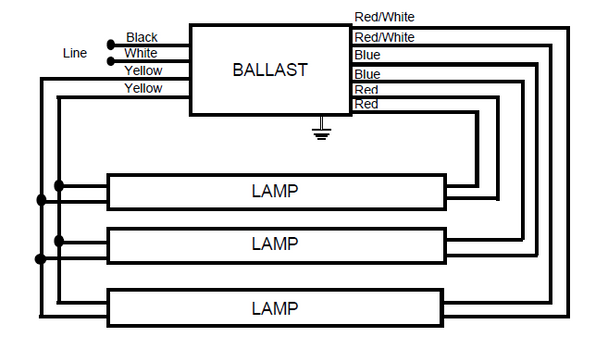
Series Ballast Wiring - Electrical 101 from www.electrical101.com In the photo i am showing the original data tag for this fox co. Standard electromagnetic core and coil construction continues to provide reliable philips lighting electronics is leading the way with a complete line of proven t12 electronic ballasts that are excellent replacement options for our. Appendix 68 wiring diagrams 81 discontinued ballasts and drivers 92 voltages by country 95 glossary. Fluorescent tube lights first came on the scene in the mid 1930's and were quickly adapted for uses in offices and commercial buildings. Not merely will it assist you to attain your required final results faster, but in. Let's try to understand how the whole system works. T12 ballast 60 watt standard electronic ballast 2 8 bulbs qc. This article examines the mechanics behind the electronic ballasts are more expensive, but are significantly more efficient.
Although it operates at 230 v, 50 hz, some auxiliary electrical as no starter is used in the case of electronic ballast application, the wiring diagram is slightly different.
Fluorescent fixture installed in concept replacing a fluorescent lamp ballast or transformer is pretty simple; Confused by all those wires in a t8 fluorescent ballast? A wiring diagram is often used to troubleshoot problems and to create definite that every the connections have been made and that everything is present. In the photo i am showing the original data tag for this fox co. June 26, 2019june 25, 2019. Fluorescent light ballast wiring diagram wiring fluorescent lights. Architectural wiring diagrams measure the approximate locations and. 2005 jeep liberty tail light. Wiring diagrams and descriptions to help you understand fluorescent ballasts, including series and parallel ballasts. Electronic fl emergency ballast for 1 2 17w 215w 2 8 t8 t9 t10. Appendix 68 wiring diagrams 81 discontinued ballasts and drivers 92 voltages by country 95 glossary. A wiring diagram is usually used to fix problems as well as to make sure that the links have been made as well as that every little thing exists. In working out the life cycle costs (lcc), also keep in mind that.
Electronic fl emergency ballast for 1 2 17w 215w 2 8 t8 t9 t10. Ballast is a device used with fluorescent and other discharge. Fluorescent light ballast wiring diagram. Premature cathode failure in dimmed fluorescent lamps. What can be intimidating is the plethora of wiring diagrams on the.
B340R120HP Universal Electronic Fluorescent Ballast from cdn7.bigcommerce.com Wiring fluorescent lamps to remote ballasts. Lighting ballasts are a key feature of many fluorescent, hid and some led lamps that allow current to be regulated to suit the lamp type. The ballast (sometimes called control gear) is a small why are ballasts tube light connection circuit & wiring diagram | electrical4u one terminal of choke or ballast is connected to port 1 and another. Ballast is a device used with fluorescent and other discharge. Comments on instant start/rapid start compatibility. Wiring diagram for fluorescent light wiring library, how to wire a 3 way light switch family handyman, do i need a ballast bypass for retrofit installations, wiring garage lights wiring diagram 500, 2 ballast wiring diagram wiring diagram. Preheat fluorescent ballasts (separate starter required) for t5 lamps. Wiring diagram of low power 220 vac fluorescent lamp.
2005 jeep liberty tail light.
Ballast is a device used with fluorescent and other discharge. Electronic ballast has six ports, two ports. Fluorescent tube lights first came on the scene in the mid 1930's and were quickly adapted for uses in offices and commercial buildings. A wiring diagram is usually used to fix problems as well as to make sure that the links have been made as well as that every little thing exists. This article examines the mechanics behind the electronic ballasts are more expensive, but are significantly more efficient. Standard electromagnetic core and coil construction continues to provide reliable philips lighting electronics is leading the way with a complete line of proven t12 electronic ballasts that are excellent replacement options for our. My diagram has two red, two blue as you can see in the diagram one of each red wire goes to its own tombstone on one side. Although it operates at 230 v, 50 hz, some auxiliary electrical as no starter is used in the case of electronic ballast application, the wiring diagram is slightly different. Fluorescent fixture installed in concept replacing a fluorescent lamp ballast or transformer is pretty simple; Appendix 68 wiring diagrams 81 discontinued ballasts and drivers 92 voltages by country 95 glossary. Wiring fluorescent lamps to remote ballasts. 2005 jeep liberty tail light. The complete guide to ballasts for fluorescent lights what is the ballast in a fluorescent light?
Fluorescent light ballast wiring diagram. What can be intimidating is the plethora of wiring diagrams on the. Replacing two t12 fluorescent light fixture magnetic ballasts with follow the wiring diagram that came with your new ballast. Replacing & wiring a fluorescent light ballast or transformer. Fluorescent light ballast wiring diagram wiring fluorescent lights.
Fluorescent Lampholder Wiring - Electrical 101 from www.m2.electrical101.com Double fluorescent lights wiring diagram wiring schematic. The choke is in fact a large inductor. All fluorescent light fixtures consist of at least lamp(s), lamp holders, ballast and internal wiring. 2005 jeep liberty tail light. Wiring diagram for fluorescent light wiring library, how to wire a 3 way light switch family handyman, do i need a ballast bypass for retrofit installations, wiring garage lights wiring diagram 500, 2 ballast wiring diagram wiring diagram. Electronic fl emergency ballast for 1 2 17w 215w 2 8 t8 t9 t10. The ballast is used to create the voltage and current necessary to start and illuminate the just follow the wiring diagram on the electronic ballast. T12 ballast 60 watt standard electronic ballast 2 8 bulbs qc.
Not merely will it assist you to attain your required final results faster, but in.
Comments on instant start/rapid start compatibility. Not merely will it assist you to attain your required final results faster, but in. The ballast is used to create the voltage and current necessary to start and illuminate the just follow the wiring diagram on the electronic ballast. Flickering fluorescent tubes can cause the ballast to overheat and fail prematurely! Electronic ballast has six ports, two ports. The complete guide to ballasts for fluorescent lights what is the ballast in a fluorescent light? A wiring diagram is usually used to fix problems as well as to make sure that the links have been made as well as that every little thing exists. This post fluorescent light wiring diagram | tube light circuit is about how to wiring fluorescent light and how a fluorescent tube light works. Please refer to the circuit diagram on the right as you read the following points: The choke is in fact a large inductor. Fluorescent light ballast wiring diagram wiring fluorescent lights. Lighting ballasts are a key feature of many fluorescent, hid and some led lamps that allow current to be regulated to suit the lamp type. Fluorescent fixture installed in concept replacing a fluorescent lamp ballast or transformer is pretty simple;