Home
› Xor Ladder Logic Diagram : Relay Logic Diagram Of Xor Gate Sata Power Wiring Diagram Contuor Bonek Jeanjaures37 Fr : These blocks can be strung together to complete an entire program.
Xor Ladder Logic Diagram : Relay Logic Diagram Of Xor Gate Sata Power Wiring Diagram Contuor Bonek Jeanjaures37 Fr : These blocks can be strung together to complete an entire program.
Xor Ladder Logic Diagram : Relay Logic Diagram Of Xor Gate Sata Power Wiring Diagram Contuor Bonek Jeanjaures37 Fr : These blocks can be strung together to complete an entire program.. These blocks can be strung together to complete an entire program. It is a graphical plc programming language which expresses logic operations with symbolic notation. Ladder logic (also known as ladder diagram or ld) is a programming language used to program a plc (programmable logic controller). 1 programming plcs (logic functions) and consider a control system with two inputs, a and b and there is an output only when both a and b are both on 1 indicates an on signal, 0 an off signal the output is 1 or on when both a and b are 1s or on the truth table for the and gate: It is suited where binary variables are required and where interlocking and sequencing of a binary is the primary control problem.
That is, a true output results if one, and only one, of the inputs to the gate is true. If one input goes true, the output is off. Save my name, email, and website in this browser for the next time i comment. A.) filling a tank to a predetermined level b.) agitating the liquid for 30 minutes c.) draining the tank for use in another part of process does the ladder logic schematic that follows perform The ladder logic implementation of xor gate is shown in below figure.
Basic Ladder Diagram Logic Functions Plc Programmable Logic Controllers Industrial Automation Plc Programming Scada Pid Control System from forumautomation.com The bitwise xor instruction is a ladder logic rung output instruction that performs an xor operation on source a and source b and places the result in the destination tag. Ladder diagram example a manual mixing operation is to be automated using sequential process control methods. Figure 11 shows a ladder diagram for an xor gate system. Types of logic gates using plc ladder. In general // on a ladder diagram contacts in a horizontal rung, i.e., contacts in series, represent the logical and operations. These diagrams documented how connections between devices were made on relay panels; This is, of course, a generic example and you'll have to adapt it to your specific plc. A.) filling a tank to a predetermined level b.) agitating the liquid for 30 minutes c.) draining the tank for use in another part of process does the ladder logic schematic that follows perform
Welcome !!!this video will help you to understand how to use or gate logic in ladder diagram.
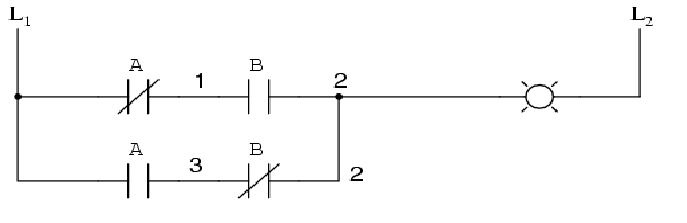
The ladder logic implementation of xor gate is shown in below figure. The ladder logic to implement an xor gate is a little more complex then the others. We compared and and or logic function blocks with their ladder logic counterpart. So the conversion to ladder diagram, logic xor similarly, the logic of the previous ones. When just input a is activated, then the upper branch results in the output being 1. The ladder logic implementation of xor gate is shown in below figure: The instruction is enabled when the preceding logic is true and disabled otherwise. Otherwise, the output turns on. As you can see for the similar inputs the output is low, while for the dissimilar inputs the output is high. We have placed x0 and x1 in series and also in parallel, but in first string x0 is normally open and x1 is normally closed while in second string x0 is normally closed and x1 is normally open. If we use standard binary notation for the status of the switches and lamp (0 for unactuated or. When just input b is activated, then the lower branch results in the output being 1. The safest way is to apply it to the output.
Essentially, a single function block can take the place of an entire line of ladder logic. The bitwise xor instruction is a ladder logic rung output instruction that performs an xor operation on source a and source b and places the result in the destination tag. Otherwise, the output turns on. The instruction is enabled when the preceding logic is true and disabled otherwise. Different types of ladder logic diagram that perform different logic gate functions.
Programmable Logic Controllers Part 2 from www.industrial-electronics.com Figure 11 shows a ladder diagram for an xor gate system. We have placed x0 and x1 in series and also in parallel, but in first string x0 is normally open and x1 is normally closed while in second string x0 is normally closed and x1 is normally open. Essentially, a single function block can take the place of an entire line of ladder logic. This looks a bit complex but trust me it's really easy after you make the same ladder logic diagram in the winproladder software you will understand how this actually works. It's the same as feeding the output from the xor through a not. When just input b is activated, then the lower branch results in the output being 1. If one input goes true, the output is off. When input a and input b are not activated then there is 0 output.
It is suited where binary variables are required and where interlocking and sequencing of a binary is the primary control problem.
Essentially, a single function block can take the place of an entire line of ladder logic. Click on the following equations to draw. When just input a is activated, then the upper branch results in the output being 1. We compared and and or logic function blocks with their ladder logic counterpart. The video tells you every condition related to t. The ladder logic to implement an xor gate is a little more complex then the others. It's the same as feeding the output from the xor through a not. 2/4/2021 plc programming 2 and… ladder diagram for the implementation of the and operation the timing diagram for. Otherwise, the output turns on. Ladder logic is the basis of most control functions ladder logic uses switch or relay contacts to implement boolean expressions. An xor gate is implemented like this in ladder logic. The manual also includes a reference section that describes the syntax and functions of the language elements of ladder logic. The structure behind ladder logic is based on the electrical ladder diagrams that were used with relay logic.
The safest way is to apply it to the output. We compared and and or logic function blocks with their ladder logic counterpart. This logic is also the development of and, or and not. A.) filling a tank to a predetermined level b.) agitating the liquid for 30 minutes c.) draining the tank for use in another part of process does the ladder logic schematic that follows perform Xor gate plc ladder logic diagram:
Logic Gates Programming In Plc Programmable Logic Controller Logic Gate from imgv2-1-f.scribdassets.com Save my name, email, and website in this browser for the next time i comment. The xnor gate (sometimes enor, exnor or nxor and pronounced as exclusive nor) is a digital logic gate whose function is the logical complement of the exclusive or gate. Types of logic gates using plc ladder. This is, of course, a generic example and you'll have to adapt it to your specific plc. It is suited where binary variables are required and where interlocking and sequencing of a binary is the primary control problem. Different types of ladder logic diagram that perform different logic gate functions. We compared and and or logic function blocks with their ladder logic counterpart. If both switches are in the same position then the light will be off.
Otherwise, the output turns on.
Welcome !!!this video will help you to understand how to use or gate logic in ladder diagram. Figure 3a shows an electrical circuit where an output is energized when switch a or b, both normally open, are closed. 1 for actuated or energized), a truth table can be made to show how the logic works: For this one, notice that the ladder logic diagram has an internal relay connected in a break manner in order to negate the result. Essentially, a single function block can take the place of an entire line of ladder logic. You can also follow us on facebook and twitter to receive daily updates. Xor gate (sometimes eor, or exor and pronounced as exclusive or) is a digital logic gate that gives a true (1 or high) output when the number of true inputs is odd. You probably use the xor gate everyday without thinking about it if you have a room with a light that works off two switches. When just input b is activated, then the lower branch results in the output being 1. Let's take a closer look at the formal diagram for the xnor: This is, of course, a generic example and you'll have to adapt it to your specific plc. This logic is widely used in summing strand (adder). An xor gate is implemented like this in ladder logic.