Home
› Egs002 Inverter Circuit Diagram Pdf - Diy Cheap 1000w Pure Sine Wave Inverter 12v To 110v 220v 26 Steps With Pictures Instructables : 13 x 19 = 247 vdc output.
Egs002 Inverter Circuit Diagram Pdf - Diy Cheap 1000w Pure Sine Wave Inverter 12v To 110v 220v 26 Steps With Pictures Instructables : 13 x 19 = 247 vdc output.
Egs002 Inverter Circuit Diagram Pdf - Diy Cheap 1000w Pure Sine Wave Inverter 12v To 110v 220v 26 Steps With Pictures Instructables : 13 x 19 = 247 vdc output.. The usual aspects in a wiring diagram are ground, power supply, cable as well as connection, result tools, buttons, resistors, reasoning gateway, lights, etc. Ir2110 floating circuit can drive high side mosfet up to 500 volts. This project i use the egs002 module. This is a simple sine wave inverter circuit without programming. Implementation of an egs002 with ardunio nano.
How to build a 1kva inverter steemit solar inverter of family appliances pcb layout design id 6156766 inverter sine 12v to 220v egs002 irf1404 circuit how to make how to make solar inverter circuit share this post. Dimension diagram egs002 dimension diagram 图5‐1. If you like the work and intend to build the cir… The home inverter overall structure is, downside is a large cooling plate, upside is a power board with same size as the cooling plate, length 228mm, width 140mm. After two build tries, i could check the seller is trickster, unfortunately.there are several.
Egs002ç"¨æˆ·æ‰‹å†Œv1 0 Enx Egs002 Manual En from usermanual.wiki Circuit is h bridge design, using 4 mosfet. A relatively simple 1000 watt pure sine wave inverter circuit is explained here using a signal amplifier and a power transformer. Currently im supplying input from dc supply not a battery. Egmicro, alldatasheet, datasheet, datasheet search site for electronic components and semiconductors, integrated circuits, diodes, triacs, and other semiconductors. Pure sine wave inverter circuit with no center tap design has become simple by using egs002 sinusoidal inverter driver card. 250 to 5000 watts pwm dc/ac 220v power inverter: Transformerless inverter block diagram dc power source: Sinusoid inverter driver board, egs002 datasheet, egs002 circuit, egs002 data sheet :
Currently im supplying input from dc supply not a battery.
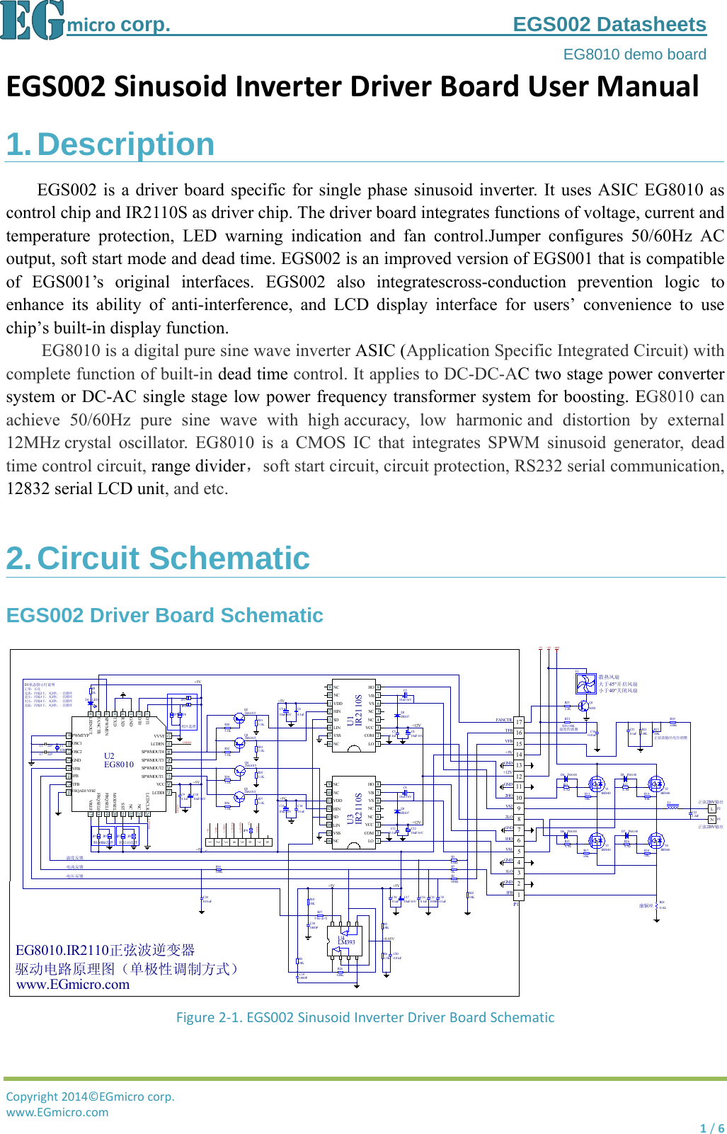
3 phase inverter circuit diagram. Project today , i will test inverter 500w max peak, use 4 mosfet irf1404. Hi guys, i'm from brazil, friendly to digital electronic and microcontrollers (pic, arm, arduino, etc.), but a completely dummy in analog eletronic, mainly using op amps. Voltage value at vfb/pa and ifb/pa 5. The internet is flooded with single phase inverter circuit diagrams, but there are only few circuit diagrams of 3 phase inverter out there, a simplest possible 3 phase inverter is described here. With inverter power ranging from 300w to over 10,000 watts net, with this module we can build pure sine wave inverters at low prices with the same wave output. This project i use the egs002 module. So i can send my circuit diagram and some details Pure sine wave inverter circuit with no center tap design has become simple by using egs002 sinusoidal inverter driver card. Specification of t1,t3,t4,t5 and t6 4. Egs002 spwm rc filter circuit figure 4‐3.output waveform of test 2 andtest3 5. Block diagram of transformerless inverter circuit: Descriptionegs002 is a driver board specific for single phase sinusoid inverter.
3 phase inverter circuit diagram. Project today , i will test inverter 500w max peak, use 4 mosfet irf1404. Here is the circuit section, get understanding the basics of this power inverter, diy an inverter now. Where we connect j1 and j2. Three phase inverters require microcontroller design where the timings of the all three phases need to be precisely.
Module Usb Picture More Detailed Picture About Pure Sine Wave Inverter Driver Board Egs002 Eg8010 Ir2110 Driver Module Free Shipping Picture In Inverters from i.pinimg.com Egs002 sine wave inverter circuit. Ir2110 floating circuit can drive high side mosfet up to 500 volts. I only getting output around 5v before connect to transformer. Dimension diagram egs002 dimension diagram 图5‐1. To read a wiring diagram, initially you need to know just what essential aspects are consisted of in a wiring diagram, and which pictorial symbols are made use of to represent them. Hi guys, i'm from brazil, friendly to digital electronic and microcontrollers (pic, arm, arduino, etc.), but a completely dummy in analog eletronic, mainly using op amps. Egmicro, alldatasheet, datasheet, datasheet search site for electronic components and semiconductors, integrated circuits, diodes, triacs, and other semiconductors. It has undervoltage, overvoltage, overcurrent protection, overcurrent protection is implemented by test tube drop.
The usual aspects in a wiring diagram are ground, power supply, cable as well as connection, result tools, buttons, resistors, reasoning gateway, lights, etc.
How to use a wiring diagram a home or vehicle is a maze of wiring and connections, making repairs and improvements a complex endeavor for some. However, today i will test with a pwm sine mo. Egs002 sine wave inverter circuit. 3 phase inverter circuit diagram. Below is the circuit diagram of dspic30f2010 3 interleaved buck mppt charger controller circuit. It can also be used as an igbt driver. This project i use the egs002 module. To read a wiring diagram, initially you need to know just what essential aspects are consisted of in a wiring diagram, and which pictorial symbols are made use of to represent them. Egs002 driver board dimension diagram egs002 eg8010 + r2110s spwm driver board 6.0±0.2 32±0.3 61±0.3 1.9±0.1 250 to 5000 watts pwm dc/ac 220v power inverter: Where we connect j1 and j2. Where we connect p3 and p7 3. Detail egs002 inverter circuit diagram pdf dapat kamu nikmati dengan cara klik link download dibawah dengan mudah tanpa adanya iklan yang mengganggu.
Where we connect j1 and j2. So i can send my circuit diagram and some details Can i get your email. Egs002 spwm rc filter circuit figure 4‐3.output waveform of test 2 andtest3 5. The home inverter overall structure is, downside is a large cooling plate, upside is a power board with same size as the cooling plate, length 228mm, width 140mm.
Egs002ç"¨æˆ·æ‰‹å†Œv1 0 Enx Egs002 Manual En from usermanual.wiki Implementation of an egs002 with ardunio nano. Here is the circuit section, get understanding the basics of this power inverter, diy an inverter now. Sine wave inverter circuit description. Hi guys, i'm from brazil, friendly to digital electronic and microcontrollers (pic, arm, arduino, etc.), but a completely dummy in analog eletronic, mainly using op amps. Egs002 spwm rc filter circuit figure 4‐3.output waveform of test 2 andtest3 5. To read a wiring diagram, initially you need to know just what essential aspects are consisted of in a wiring diagram, and which pictorial symbols are made use of to represent them. Project today , i will test inverter 500w max peak, use 4 mosfet irf1404. Ir2210 can withstand voltage up to 500v (offset voltage).
13 x 19 = 247 vdc output.
Sine wave inverter circuit description. So i can send my circuit diagram and some details It can also be used as an igbt driver. Ir2110 floating circuit can drive high side mosfet up to 500 volts. Block diagram of transformerless inverter circuit: If you like the work and intend to build the cir… 250 to 5000 watts pwm dc/ac 220v power inverter: Descriptionegs002 is a driver board specific for single phase sinusoid inverter. Read readme.pdf how to do it. Egs002 sine wave inverter circuit. How to build a 1kva inverter steemit solar inverter of family appliances pcb layout design id 6156766 inverter sine 12v to 220v egs002 irf1404 circuit how to make how to make solar inverter circuit share this post. This is a heavy duty design of a pulse width modulator dc/ac inverter using the chip sg3524. Hi guys, i'm from brazil, friendly to digital electronic and microcontrollers (pic, arm, arduino, etc.), but a completely dummy in analog eletronic, mainly using op amps.