Wall Switch Wiring Diagram / Switched Outlet Wiring... in 2020 | Outlet wiring, Outlet, Switch : Switch wiring shows the power source (power in) starts at the switch box.. Question about neutral wire through wall switch. Wall light switch wiring neuro ticcom. Ceiling fan 3 speed wall switch wiring diagram. A wiring diagram is often utilized to troubleshoot issues and making sure that all the connections have actually been made as well as that everything dimension: As with all things electrical, safety is a real issue, so you need to know how to wire a wall switch safely, securely, and easily.
As with all things electrical, safety is a real issue, so you need to know how to wire a wall switch safely, securely, and easily. Wall light switch wiring neuro ticcom. Collection of ceiling fan 3 speed wall switch wiring diagram. Just use your mouse pointer on this diagram and follow the current flow from a relay is basically a switch but not like a switch that's on a wall. Click on the image to enlarge, and then save it to your computer.
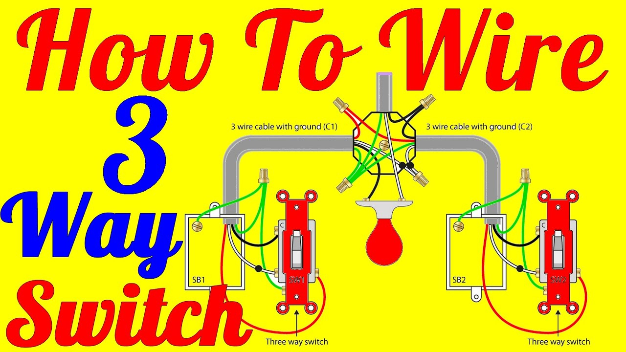
wall switch wiring diagrams - My Engineering from i1.wp.com Wiring diagrams use simplified symbols to represent switches, lights, outlets, etc. The schematic is nice and simple to visualise the principal of how a two way switch works but is little help when it coms to actually wiring this up in real life!! Every sort of switch is going to have a different symbol and so will the several outlets. The diagram explains that the power source is coming in. Two way switching schematic wiring diagram (3 wire control). A line diagram and wiring schematic of a basic single pole switch circuit with 3 lights. Therefore, from wiring diagrams, you understand the relative location of the constituents and just how they are connected. If you only have 2 wires at the light, and 2 at the switch, the light would not work.
Wiring wall dimmer electrical wiring diagram.
It shows the components of the circuit as simplified shapes, and the gift and signal associates in the midst of the devices. A line diagram and wiring schematic of a basic single pole switch circuit with 3 lights. Wiring wall dimmer electrical wiring diagram. Therefore, from wiring diagrams, you understand the relative location of the constituents and just how they are connected. Feit electric digital slide dimmer ideal for led lighting 2pack 1600078. Are the example of secondary equipment. As with all things electrical, safety is a real issue, so you need to know how to wire a wall switch safely, securely, and easily. The schematic is nice and simple to visualise the principal of how a two way switch works but is little help when it coms to actually wiring this up in real life!! In this diagram, the black wire of the ceiling fan is for the fan, and the blue wire is for the light kit. 240 volt photocell wiring diagram download. Just a bit of backstory on why i put this article together: If you encounter any difficulties installing/wiring your dry contact wall switch, call your dealer or draper, inc., spiceland, ind., (765). Click on the image to enlarge, and then save it to your computer by right.
Wiring wall dimmer electrical wiring diagram. Electric wall switches last a long time. It makes no difference which hot wire (input or output) goes to which brass screw, but most electricians follow a consistent pattern when wiring them into branch. Fig 2 below shows how we achieve this configuration. Wiring for multiple outlet this diagram illustrates wiring for a 4 way circuit with 3 way switch the electrical source at the light fixture and the wiring switches.
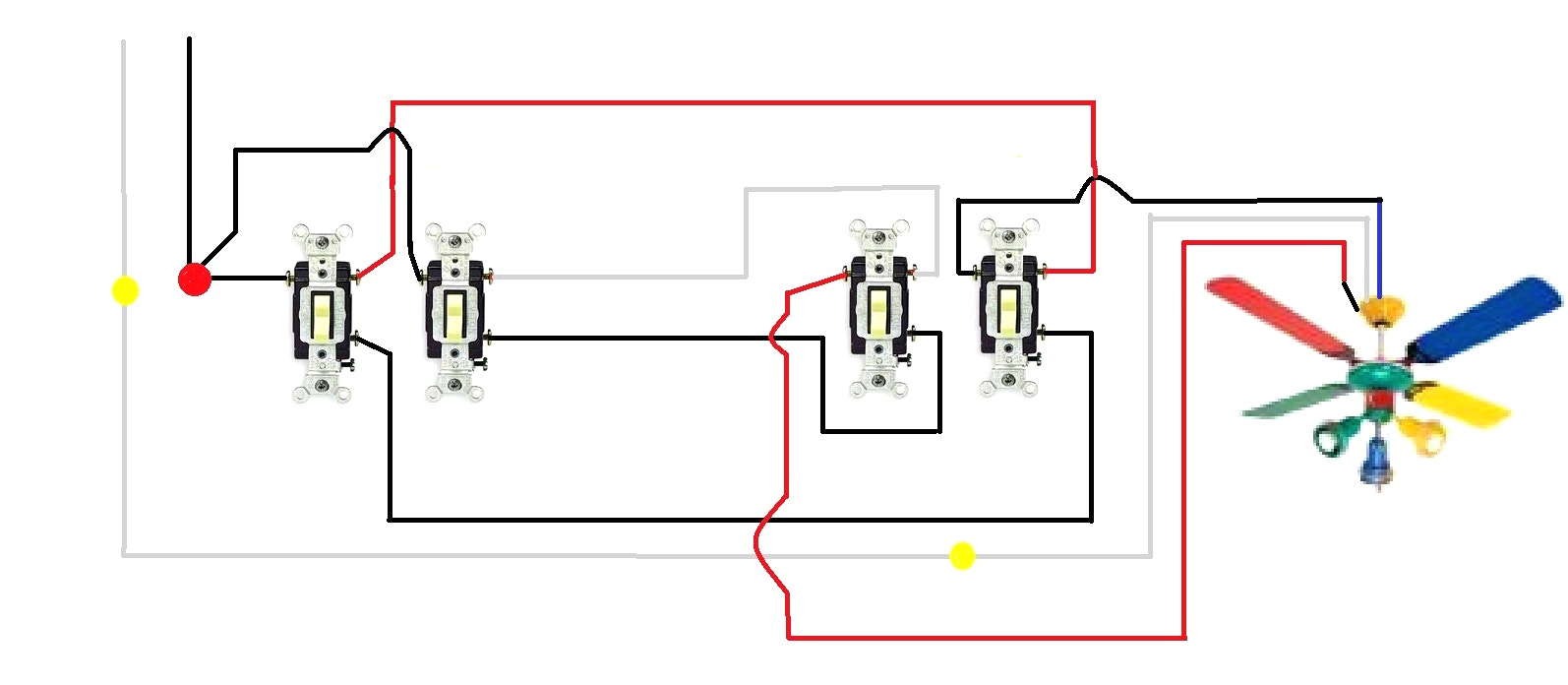
Ceiling Fan Wall Switch Wiring Diagram | Wiring Diagram from 2020cadillac.com Wiring your light switches sounds like a headache for another person (a professional electrician, to be more specific), but it can become a simple task when some groundwork is laid out for you, as what i am going to do for this article. If you only have 2 wires at the light, and 2 at the switch, the light would not work. Fan regulator wiring diagram हमारी वेबसाईट website www.shelectricalwork.com instragram. It shows the components of the circuit as simplified shapes, and the gift and signal associates in the midst of the devices. In this diagram, the black wire of the ceiling fan is for the fan, and the blue wire is for the light kit. Variety of ceiling fan 3 speed wall switch wiring diagram. Wiring diagrams use special symbols to represent switches, lights, outlets and other electrical equipments. Wiring diagrams use simplified symbols to represent switches, lights, outlets, etc.
Learn how to wire a single pole switch.
In this diagram, the black wire of the ceiling fan is for the fan, and the blue wire is for the light kit. Here is the wiring symbol legend, which is a detailed documentation of common symbols that are used in. Additional wiring diagrams can be found in the installation diagrams section. It shows the components of the circuit as simplified shapes, and the gift and signal associates in the midst of the devices. A wiring diagram is typically made use of to repair problems and making certain that the connections have actually been made and that everything exists. A wiring diagram generally offers details regarding the relative placement and also arrangement of devices and terminals on the tools, to assist in dimension: You are missing a pair of wires. Light sensors for outside lights. Collection of ceiling fan 3 speed wall switch wiring diagram. The schematic is nice and simple to visualise the principal of how a two way switch works but is little help when it coms to actually wiring this up in real life!! If you encounter any difficulties installing/wiring your dry contact wall switch, call your dealer or draper, inc., spiceland, ind., (765). Wiring for multiple outlet this diagram illustrates wiring for a 4 way circuit with 3 way switch the electrical source at the light fixture and the wiring switches. A wiring diagram is a type of schematic which utilizes abstract photographic icons to reveal all the interconnections of elements in a system.
It shows the components of the circuit as simplified shapes, and the gift and signal associates in the midst of the devices. How to wire 4 way switches. There are only three connections to be made, after all. Question about neutral wire through wall switch. A wiring diagram is a type of schematic which utilizes abstract photographic icons to reveal all the interconnections of elements in a system.
Three Way Light Switching | Intermediate Switch - Youtube - 3Way Switch Wiring Diagram | Wiring ... from annawiringdiagram.com As with all things electrical, safety is a real issue, so you need to know how to wire a wall switch safely, securely, and easily. Every sort of switch is going to have a different symbol and so will the several outlets. A wiring diagram is often utilized to troubleshoot issues and making sure that all the connections have actually been made as well as that everything dimension: Table of content protection and signalization relays, miniature circuit breakers, selector switches, auxiliary relays, signal lights, etc. Wiring diagrams use simplified symbols to represent switches, lights, outlets, etc. Collection of ceiling fan 3 speed wall switch wiring diagram. Form drycontactwallswitch_wiring15 printed in u.s.a. A wiring diagram generally offers details regarding the relative placement and also arrangement of devices and terminals on the tools, to assist in dimension:
Click on the image to enlarge, and then save it to your computer.
240 volt photocell wiring diagram download. It makes no difference which hot wire (input or output) goes to which brass screw, but most electricians follow a consistent pattern when wiring them into branch. Icons that represent the components in the circuit, and lines that stand for the connections between them. Form drycontactwallswitch_wiring15 printed in u.s.a. Therefore, from wiring diagrams, you understand the relative location of the constituents and just how they are connected. Wiring diagrams use simplified symbols to represent switches, lights, outlets, etc. A wiring diagram is a type of schematic which utilizes abstract photographic icons to reveal all the interconnections of elements in a system. Fig 2 below shows how we achieve this configuration. How to add a light. Electric wall switches last a long time. A wiring diagram is often utilized to troubleshoot issues and making sure that all the connections have actually been made as well as that everything dimension: This diagram is a thumbnail. A wiring diagram is a visual representation of components and wires related to an electrical connection.