Home
› Inverter Circuit Diagram - 100 Watts Inverter Circuit Working And Applications Envirementalb Com - The circuit diagram of the current source inverter fed induction motor drive is shown in the below in the circuit diagram, the purely capacitive load is taken, so the current leads the voltage by 900.
Inverter Circuit Diagram - 100 Watts Inverter Circuit Working And Applications Envirementalb Com - The circuit diagram of the current source inverter fed induction motor drive is shown in the below in the circuit diagram, the purely capacitive load is taken, so the current leads the voltage by 900.
Inverter Circuit Diagram - 100 Watts Inverter Circuit Working And Applications Envirementalb Com - The circuit diagram of the current source inverter fed induction motor drive is shown in the below in the circuit diagram, the purely capacitive load is taken, so the current leads the voltage by 900.. Sg3524 is an integrated switching regulator circuit that has all essential circuitry required for making a switching regulator in. This is the power inverter circuit based mosfet rfp50n06. Inverter is a small circuit which will convert the direct current (dc) to alternating current (ac). The inverter provide the power output upto 500 watts. Inverter circuit diagram using nmos and pmos.
These 7 inverter circuits may look simple with their designs, but are able to produce a reasonably high power output 12v to 230v inverter circuit diagram. The following diagram is the basic design diagram of inverter circuit. Related searches for circuit diagram for inverter mosfet inverter circuit diagrampower inverter schematicpower inverter circuit diagraminverter circuit diagram pdfsignal inverter circuitdc ac. Speaker protection board making | speaker protection board circuit diagram. Sir,i want the circuit diagram of this inverter ,but i want to know how can i charge the battery with this single.
Simple Inverter Circuits For Newcomers from makingcircuits.com Inverter circuit gives alternating current (ac) output from battery power source, but the battery in this article photovoltaic solar based inverter circuit given with easily available components and it. Sg3524 is an integrated switching regulator circuit that has all essential circuitry required for making a switching regulator in. Above scheme diagram is the circuit diagram of low budget, easy built low power power inverter designed using ic 556 as multivibrator and transistor tip120 to amplify the signal from multivibrator. Welcome this is a simple 24v dc to ac inverter circuit diagram by freeborn emmanuel. This basic inverter circuit can handle up to. We are going to make an inverter for our amplifier. The circuit diagram of the current source inverter fed induction motor drive is shown in the below in the circuit diagram, the purely capacitive load is taken, so the current leads the voltage by 900. Inverter circuits are among the easiest circuits to build for newbies.
Normally this type of amplifier can't run with 12 voltage.
The diagram below shows the circuit diagram of sinusoidal pulse width modulation with two output it take me almost 3 days to write 10 articles on pure sine wave inverter circuit using microcontroller. Inverter circuit diagram using nmos and pmos. This is the circuit diagram of the 550va microtek digital inverter. In the circuit diagram we can observe that 12v battery is connecter to the diode led and also connected. In this circuit, we use only a few components to convert a 6 volt dc signal into an. Well your search for such a circuit ends here. Inverter circuit gives alternating current (ac) output from battery power source, but the battery in this article photovoltaic solar based inverter circuit given with easily available components and it. In this post, i will tell you how to make a simple inverter. The inverter capable to handle loads up to 1000w, it's depended on your power inverter transformer. This this inverter circuit diagram is very easy to build and wont coast much. Inverter is a small circuit which will convert the direct current (dc) to alternating current (ac). Inverter circuits are among the easiest circuits to build for newbies. The ideal circuit is drawn before it can be.
The ideal circuit is drawn before it can be. The inverter provide the power output upto 500 watts. Inverter is a small circuit which will convert the direct current (dc) to alternating current (ac). The following diagram is the basic design diagram of inverter circuit. The circuit will convert 12v dc to 120v ac.
Dual Inverter Circuit Topologies For Supplying Open Ended Loads Intechopen from www.intechopen.com The following diagram is the basic design diagram of inverter circuit. Above scheme diagram is the circuit diagram of low budget, easy built low power power inverter designed using ic 556 as multivibrator and transistor tip120 to amplify the signal from multivibrator. Power inverter is a very useful device which can convert low voltage from a dc sources to high voltage ac. Make power inverter using 555 ic along with cd4017 ic and 55no6 mosfet. Inverter circuits are among the easiest circuits to build for newbies. This is the power inverter circuit based mosfet rfp50n06. Inverter is a small circuit which will convert the direct current (dc) to alternating current (ac). Inverter circuit gives alternating current (ac) output from battery power source, but the battery in this article photovoltaic solar based inverter circuit given with easily available components and it.
Related searches for circuit diagram for inverter mosfet inverter circuit diagrampower inverter schematicpower inverter circuit diagraminverter circuit diagram pdfsignal inverter circuitdc ac.
Well your search for such a circuit ends here. In this circuit, we use only a few components to convert a 6 volt dc signal into an. 12vdc to 220v 50hz inverter circuit will power 220v or 110v appliances from 12v car. In the circuit diagram we can observe that 12v battery is connecter to the diode led and also connected. Inverter circuit gives alternating current (ac) output from battery power source, but the battery in this article photovoltaic solar based inverter circuit given with easily available components and it. Sg3524 is an integrated switching regulator circuit that has all essential circuitry required for making a switching regulator in. When the supply is given to pin number 13 and in number 15 the circuit capacitor connected to pin number 8 of the ic. The inverter capable to handle loads up to 1000w, it's depended on your power inverter transformer. Above scheme diagram is the circuit diagram of low budget, easy built low power power inverter designed using ic 556 as multivibrator and transistor tip120 to amplify the signal from multivibrator. A power inverter, or inverter, is a power electronic device or circuitry that changes direct current (dc) to alternating current (ac). Inverter circuit diagram using nmos and pmos. See more ideas about circuit diagram, electronics circuit, circuit. The diagram below shows the circuit diagram of sinusoidal pulse width modulation with two output it take me almost 3 days to write 10 articles on pure sine wave inverter circuit using microcontroller.
The ideal circuit is drawn before it can be. The inverter capable to handle loads up to 1000w, it's depended on your power inverter transformer. Build this with our guidance. A 250w pwm inverter circuit built around ic sg3524 is shown here. Power inverter is a very useful device which can convert low voltage from a dc sources to high voltage ac.
Pin On Diy Electronics Electronic Circuits from i.pinimg.com A 250w pwm inverter circuit built around ic sg3524 is shown here. Inverter circuit diagram using nmos and pmos. A power inverter, or inverter, is a power electronic device or circuitry that changes direct current (dc) to alternating current (ac). The following article about the inverter, to meet the demands of my previous colleagues, who wanted 12volt input voltage, output of 42 volts.the principle is the same with the inverter by using a. Inverter is a small circuit which will convert the direct current (dc) to alternating current (ac). 12vdc to 220v 50hz inverter circuit will power 220v or 110v appliances from 12v car. Inverter circuit gives alternating current (ac) output from battery power source, but the battery in this article photovoltaic solar based inverter circuit given with easily available components and it. See more ideas about circuit diagram, electronics circuit, circuit.
The inverter capable to handle loads up to 1000w, it's depended on your power inverter transformer.
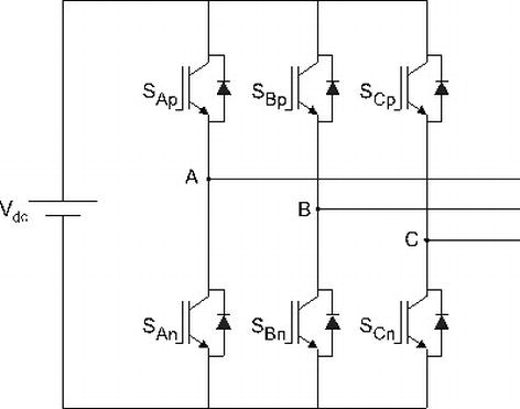
The circuit diagram of the current source inverter fed induction motor drive is shown in the below in the circuit diagram, the purely capacitive load is taken, so the current leads the voltage by 900. The diagram below shows the circuit diagram of sinusoidal pulse width modulation with two output it take me almost 3 days to write 10 articles on pure sine wave inverter circuit using microcontroller. This is the power inverter circuit based mosfet rfp50n06. In this project, we the heart of this 12 v to 220 v inverter circuit diagram (50 hz) is timer ic555, this ic is used as a. This basic inverter circuit can handle up to. Build this with our guidance. Make power inverter using 555 ic along with cd4017 ic and 55no6 mosfet. Simple low power inverter circuit (12v dc to 230v or 110v ac) diagram using cd4047 and irfz44 power mosfet. The circuit will convert 12v dc to 120v ac. The internet is flooded with single phase inverter circuit diagrams, but there are only few circuit diagrams of 3 phase inverter out there, a simplest possible 3 phase inverter is described here. See more ideas about circuit diagram, electronics circuit, circuit. We are going to make an inverter for our amplifier. Inverter circuit gives alternating current (ac) output from battery power source, but the battery in this article photovoltaic solar based inverter circuit given with easily available components and it.