Home
› Types Of Electrical Circuits Diagrams : Electrical Wire Types Pdf Perfect 2016 Toyota Electrical Wiring Diagrams, Wiring Diagram U2022 ... : A circuit diagram is a visual display of an electrical circuit.
Types Of Electrical Circuits Diagrams : Electrical Wire Types Pdf Perfect 2016 Toyota Electrical Wiring Diagrams, Wiring Diagram U2022 ... : A circuit diagram is a visual display of an electrical circuit.
Types Of Electrical Circuits Diagrams : Electrical Wire Types Pdf Perfect 2016 Toyota Electrical Wiring Diagrams, Wiring Diagram U2022 ... : A circuit diagram is a visual display of an electrical circuit.. What is an electric circuit? A simple electric circuit consists of a source (such as a battery), wires as conducting medium and a load (such as a light bulb). A basic electrical circuit (diagram) consists of three main components: Explaining different types of circuits including series and parallel circuits. These free electronic circuits are properly tested and can be found with schematic diagrams, breadboard image or pcb, a detailed explanation of working principle and a demonstration video.
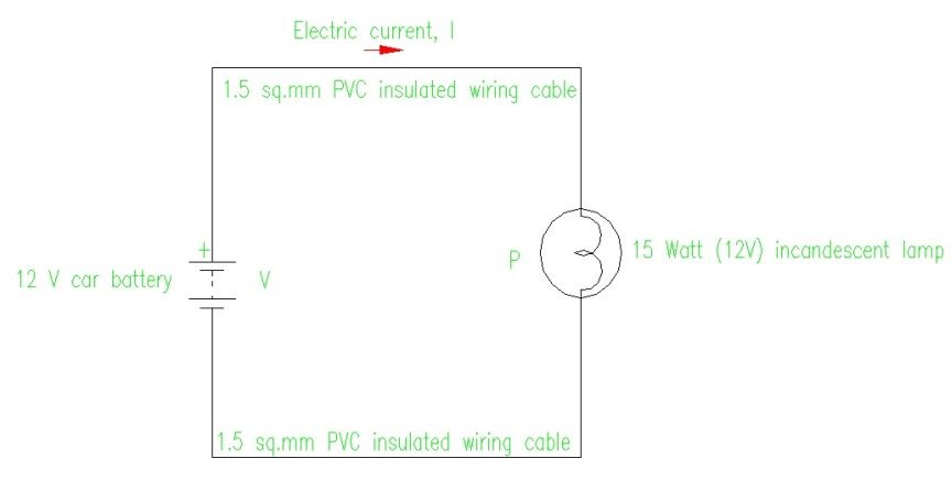
A circuit diagram (electrical diagram, elementary diagram, electronic schematic) is a graphical representation of an electrical circuit. A series circuit has only one path for electricity to flow from one point to another. Depending upon the type of current flowing, the electric circuit is classified into d.c. In this case, the value both conditions are shown in the given below diagram Electric circuit, path for transmitting electric current.
Electric Circuit Diagram Design: Electric circuit basic diagram from 3.bp.blogspot.com A pictorial circuit diagram uses simple images of components, while a schematic diagram shows the components and interconnections of the circuit using. In a home electrical circuit, for instance, the same voltage is applied across each light or appliance, but each of these loads draws a different amount two diagrams showing an ammeter connected to a simple circuit in two different positions. A series circuit has elements connected in series, or one after the other. When the switch is closed, current passes through the. Here are ten simple electric circuits from homes to big industries, we all depend on electricity. Explore simple electronics circuits and mini projects ideas. A ladder or line diagram is a diagram that shows the function of an electrical circuit using electrical symbols. Electrical circuit is an interconnection of electrical components.
Symbol usage depends on the audience viewing the diagram.
Electrical equipment and circuitry is often expressed as symbols and lines that represent the various components and connections within a system. In a home electrical circuit, for instance, the same voltage is applied across each light or appliance, but each of these loads draws a different amount two diagrams showing an ammeter connected to a simple circuit in two different positions. The remainder of lesson 4 will be devoted to a study of these two types of connections and the effect that they have upon electrical quantities such as current, resistance and electric potential. The source, the load, and the conductors. The electric circuit can be categorized in three different ways. A series circuit has elements connected in series, or one after the other. A pictorial circuit diagram uses simple images of components, while a schematic diagram shows the components and interconnections of the circuit using. A circuit diagram is a visual display of an electrical circuit. In this case, the value both conditions are shown in the given below diagram Symbol usage depends on the audience viewing the diagram. A conductive wire is used to establish relation among source of voltage and load. Different types of electrical diagrams and drawing. Consider the below circuit diagram.
A series circuit has elements connected in series, or one after the other. A conductive wire is used to establish relation among source of voltage and load. Often it is useful to sketch a diagram of a circuit if you are given some combination of v, i and r types of circuits. In this article, we will learn how to draw a simple electric circuit the pictorial ckt diagram is one of the fundamental diagrams that employs simple images of electrical components. Different types of electrical diagrams and drawing.
The World Through Electricity: Types of wiring : Concealed wiring from lh4.googleusercontent.com The source, the load, and the conductors. The remainder of lesson 4 will be devoted to a study of these two types of connections and the effect that they have upon electrical quantities such as current, resistance and electric potential. A circuit diagram is a visual display of an electrical circuit using either basic images of parts or industry standard symbols. Electric circuit, path for transmitting electric current. These free electronic circuits are properly tested and can be found with schematic diagrams, breadboard image or pcb, a detailed explanation of working principle and a demonstration video. In a home electrical circuit, for instance, the same voltage is applied across each light or appliance, but each of these loads draws a different amount two diagrams showing an ammeter connected to a simple circuit in two different positions. In this article, we will learn how to draw a simple electric circuit the pictorial ckt diagram is one of the fundamental diagrams that employs simple images of electrical components. A circuit diagram is a visual display of an electrical circuit.
The point where the electrons leave an electrical circuit is called the return or earth ground.
Circuit symbols and circuit diagrams. A simple electric circuit consists of a source (such as a battery), wires as conducting medium and a load (such as a light bulb). A circuit diagram is a visual display of an electrical circuit. Schematic electrical wiring diagrams are different from other electrical wiring diagrams because they show the flow through the circuit rather than the physical layout of any equipment. When the switch is closed, current passes through the. A series circuit has elements connected in series, or one after the other. A ladder or line diagram is a diagram that shows the function of an electrical circuit using electrical symbols. A conductive wire is used to establish relation among source of voltage and load. By santosh das | last updated on november 21, 2019. Here are ten simple electric circuits from homes to big industries, we all depend on electricity. In this article, we will learn how to draw a simple electric circuit the pictorial ckt diagram is one of the fundamental diagrams that employs simple images of electrical components. Explore simple electronics circuits and mini projects ideas. An electric circuit is a closed loop with a continuous flow of electric current from the power supply to the load.
There are various elements which are used in many types of circuits depending on the. The battery has two terminals. 1 electrical diagrams and various types of drawings. These two different types of circuit diagrams are called pictorial (using basic images) or schematic style (using. The point where the electrons leave an electrical circuit is called the return or earth ground.
Electric Circuit Diagram Design: Electric circuit basic diagram from 3.bp.blogspot.com Engineers use different types of electrical drawings to illuminate some aspects of the system but the physical circuit and its function are still the same. 1 electrical diagrams and various types of drawings. Schematic electrical wiring diagrams are different from other electrical wiring diagrams because they show the flow through the circuit rather than the physical layout of any equipment. The battery has two terminals. Symbol usage depends on the audience viewing the diagram. A conductive wire is used to establish relation among source of voltage and load. The electric circuit can be categorized in three different ways. By santosh das | last updated on november 21, 2019.
An electrical circuit is a closed.
Electronic circuits are realized using multiple electrical and electronic components connected with each other by connecting wires or conducting wires for in these types of integrated circuits, passive components like capacitors and resistors are used however the transistors and diodes are connected. There are various elements which are used in many types of circuits depending on the. Schematic electrical wiring diagrams are different from other electrical wiring diagrams because they show the flow through the circuit rather than the physical layout of any equipment. Electric circuits can be further categorized according to their structural features into either an electrical circuit in which some of the elements are connected in series and some of the elements are. These electrical symbols are used to represent various electrical and electronic devices or functions. A series circuit has only one path for electricity to flow from one point to another. The pattern of particular interest is the sinusoidal ac waveform for voltage of fig.1. The electric circuit can be categorized in three different ways. Home electrical engineering electric circuit: When the switch is closed, current passes through the. This completes the description of the basic components of an electrical circuit in which electrical energy is channeled by way of electrical. .however, and multiple types of electrical circuits exist, all of which are vital to the efficient flow of electricity. Explore simple electronics circuits and mini projects ideas.