Wye Wiring Diagram
In addition to the diagram shown above with the dpdt switch, a wye with at least one dead end can be made fully automatic with a few relays connected to the turnout positions. It is always a b rail.
![]()
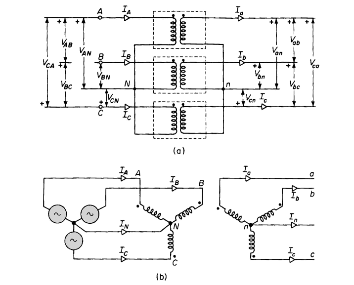
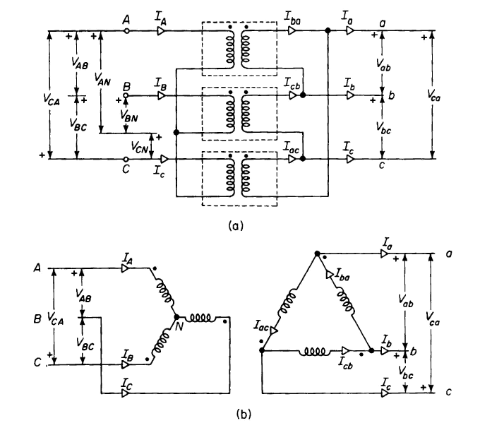
Easy understanding of 3phase transformer connections (DeltaDelta, WyeWye, DeltaWye and Wye
The original wiring diagram showed the proper arrangement of windings to create a larger wye system in which there are four equal windings between any two leads.
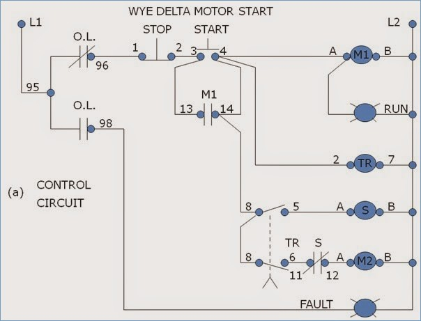
Wye wiring diagram. Wye delta motor starter wiring diagram from eectechserv.cart.net.au. To properly read a electrical wiring diagram, one has to know how typically the components in the program operate. If you study the diagram, you will see that the left rail of the tail must be an a when the.
Transformer wiring diagrams are printed on the. The delta configuration has the 3 phases connected like in a triangle. Electrical motors 12 lead, dual voltage, wye start/delta run, both voltages or 6 lead, single voltage, wye start/delta run motors designed by us motors for wye start, delta run may also be used for across the.
The name is given due to the shapes of the circuit diagrams, which look respectively like the letter y and the greek capital letter which resembles a triangle. The tail tracks could be extended as much as desired in any direction. Wye delta transformer wiring diagram.
R 1 r 2 i p i l v p v l typical heater wiring diagrams the following diagrams show typical heater wiring schematics. It shows how the electrical wires are interconnected and may also show where fixtures and components could possibly be attached to the system. This page contains circuit type and wiring diagrams for all the form #'s of meters, sockets and pans;
V p = phase voltage v l = line voltage i p = phase current i l = line current r = r1 = r2 = r3 = resistance of each branch w = wattage w delta = 3 w wye The primary wye windings are typically grounded. They don't normally have a neutral cable.
You also need to gap both stock rails. The diagram above shows the general layout of a typical wye. In delta configuration, the phase voltage is equal to the line voltage whereas in y configuration, the phase voltage is the line voltage divided by root 3 (sqrt (3) = 1.732).
A lead wye start/delta run motor has the ability to meet several starting wye delta starter or by a series of contactors in a control circuit. In my staging area i have three separate yards, the connecting track of which is in a wye configuration. In addition to the track arrangement, notice the two red marks near the top switch.
12 leads 3 phase high volts delta connected wiring configuration diagram electrical schematic diagram of a delta configured 12 leads motor so connected a lternatively, discover how to power your home. When and how to use a wiring diagram The second diagram shows the setup, wiring and gaps, that the op used to avoid a dead short when both turnouts are simultaneously pointed toward the wye.
With and without ct's and pt's, for wye, delta, and network circuits. A wiring diagram is a straightforward visual representation from the physical connections and physical layout associated with an electrical system or circuit. I don't see how they should be wired or if it is the same as for a reverse loop or if this device will not control the switch machines on a wye and simply changes the polarity.
The key to understanding wyes is that the tail (pointing up) turnout frog will never need to change polarity. For both wye and delta (balanced loads) wye and delta equivalent; In the diagram shown above you have two wyes shown, with no gaps for the.
Heating elements are basically in series on single phase power. Consequently, in wye configuration, the phase current and. The reason that the first diagram results in a dead short is due to the location of the wires from the input side of.
Single phase ac circuits where line voltage and current do not exceed thermostat rating. One of the most requested items of information that we receive is for wiring diagrams for the meters we sell. Don't bother with the gaps below the frog but gap the points as usual.
Draw the connecting wires necessary between the transformer windings, and between the. The most common voltage combinations are 220/380v ac and 277/480v ac. A three (3) element wye circuit will reduce the wattage output by 50%.
In the uk the wye diagram is also known as a star. Both bushing labels and polarity dots are shown. In this wiring setup, there are 4 windings in series between any two line leads.
For example , in case a module is usually powered up and it also sends out the signal of 50 percent the voltage and the technician will not know this, he would. I see the wiring diagram for one leg of the wye but does it also control the switch machine(s) so they are in the correct throw for the loco? In which circuit (y or delta) are the phase and line voltages equal?
Three Phase Transformer Connections Phasor Diagrams Electrical Academia

Wye delta motor control wiring diagram pdf
WyeWye Connection
![]()
Wye Delta Transformer Wiring Diagram
what is a wye connection
60 Wye Motor Connection Wiring Diagram Harness

How to identify transformer wiring


DELTA AND WYE CONNECTION (3PHASE) ELECTRICAL PROPERTIES BASICS AND TUTORIALS TRANSMISSION
Easy understanding of 3phase transformer connections (DeltaDelta, WyeWye, DeltaWye and Wye

[DIAGRAM] 1Lead Wye Start Delta Run Motor Wiring Diagram

Wye Start Delta Run Motor Wiring Diagram Free Wiring Diagram
Circuit analysis March 2012
Three Phase Transformer Connections Phasor Diagrams Electrical Academia
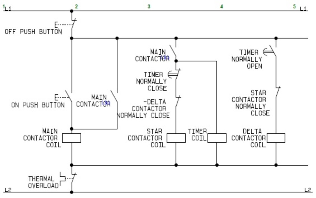
Wye Delta Starter Wiring Diagram
Wye Delta Starter Wiring Diagram

![]()
Easy understanding of 3phase transformer connections (DeltaDelta, WyeWye, DeltaWye and Wye
Wye Start Delta Run Motor Wiring Diagram Sample Wiring Diagram Sample
Wye Delta Wiring Diagram

How to connect a deltawye motor Quora