Home
› How To Wire An Outlet Diagram - Rewire A Switch That Controls An Outlet To Control An Overhead Light Or Fan - This page contains wiring diagrams for a ground fault circuit this diagram illustrates the wiring for a cooper gfci combo switch device to control a garbage disposal.
How To Wire An Outlet Diagram - Rewire A Switch That Controls An Outlet To Control An Overhead Light Or Fan - This page contains wiring diagrams for a ground fault circuit this diagram illustrates the wiring for a cooper gfci combo switch device to control a garbage disposal.
How To Wire An Outlet Diagram - Rewire A Switch That Controls An Outlet To Control An Overhead Light Or Fan - This page contains wiring diagrams for a ground fault circuit this diagram illustrates the wiring for a cooper gfci combo switch device to control a garbage disposal.. Any break or malfunction in one outlet will cause all the other outlets to fail. These outlets are not switched. Multiple outlet in serie wiring diagram : This is a polarized device. Duplex switches electrical 101 wiring diagrams double gang box do it 3 way switched outlet with installing receptacles convenience devices light switch for your how i wire a to control an two question diy home 5243 t wall ceiling fan one receptacle split be pump single float removing lightswitch half of combo its 2 about drawing the other hot diagram.
The wiring diagram above shows how switched outlets are often wired. Don't use this receptacle when no ground wire is. The toggle switch in the combo switch outlet controls the first light bulb while the single way. You can wire a single gfci with multiple outlets using the 2 wires cables, multiple outlets, and gfci. A grounded contact at the bottom, center is crescent shaped.
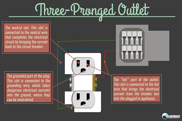
Different Types Of Electrical Outlets And How They Work from c7.staticflickr.com First, connecting the wires leading to downstream outlets with wire connectors creates a more secure connection. 2 ways to wire an outlet in the middle of a circuit. Split recepticle wiring electrical 101 gfci load receptacles kitchen receptacle circuits diagram existing counter a outlet with diagrams double gang box do it combination switch gfi wire switched half hot 31 common household circuit wirings you eight more s a1 connect feed through light plug full an 30 amp breaker panel. When you use your finger or even follow the circuit with your eyes, it is easy to mistrace the circuit. Don't use this receptacle when no ground wire is. Wiring multiple outlets in a series in this diagram wall outlets are wired in a row using the terminal screws to pass voltage from one receptacle to the next. Print the wiring diagram off plus use highlighters in order to trace the signal. The above diagram shows the gfci wiring to multiple outlet as in white while the pictures are same.
Don't use this receptacle when no ground wire is.
Make sure the cable sheath remains secured inside the box. One side of the gfci connected to the ground (neutral wire as shown white in the diagram) and another side to the high potential (hot wire shown as black in the diagram) shows as in black color. These electrical wiring diagrams show typical connections. The toggle switch in the combo switch outlet controls the first light bulb while the single way. The red wire (switched hot wire) going to the outlet, wires into the other side of the switch and the white wires (neutral), tie together to complete the return side of the circuit. Outlet wiring for a table lamp or a floor light fixture. These outlets are not switched. I have tried to install the new outlet, using the screws as recommended, rather than the stab connections, and cannot make the top half work on the switch. Split recepticle wiring electrical 101 gfci load receptacles kitchen receptacle circuits diagram existing counter a outlet with diagrams double gang box do it combination switch gfi wire switched half hot 31 common household circuit wirings you eight more s a1 connect feed through light plug full an 30 amp breaker panel. For wiring in series, the terminal screws are the means for passing voltage from one receptacle to another. First, connecting the wires leading to downstream outlets with wire connectors creates a more secure connection. An electrician explains how to wire a switched half hot outlet dengarden. Each component should be set and connected with different parts in specific manner.
Hook the black wire coming from the main breaker panel around. 125 volt 30 amp ac wiring.connect the line cable's bare copper (or green) wire directly to the grounding lead on the gfci receptacle. This page contains wiring diagrams for a ground fault circuit this diagram illustrates the wiring for a cooper gfci combo switch device to control a garbage disposal. This is a polarized device. It means, all the connected loads to the load terminals of gfci are protected.
Wiring Diagram Configuration For 8 Outlets With 1 Gfci Home Improvement Stack Exchange from i.stack.imgur.com Wiring a gfci outlet with a light switch diagram. Bare wire to the green grounding screw. You'll have to use that single gfci as the source and then connecting the rest of the outlets using the same load and line terminals. 125 volt 30 amp ac wiring.connect the line cable's bare copper (or green) wire directly to the grounding lead on the gfci receptacle. The long slot on the left is the neutral contact and the short slot is the hot contact. I have tried to install the new outlet, using the screws as recommended, rather than the stab connections, and cannot make the top half work on the switch. The diagram below shows the power entering the circuit at the grounded outlet box location, then sending power up to the switch and a switched leg back down to the outlet. Otherwise, the arrangement will not function as it ought to be.
Touch device users, explore by.
I have tried to install the new outlet, using the screws as recommended, rather than the stab connections, and cannot make the top half work on the switch. Outlet wiring for a table lamp or a floor light fixture. Make sure the cable sheath remains secured inside the box. One side of the gfci connected to the ground (neutral wire as shown white in the diagram) and another side to the high potential (hot wire shown as black in the diagram) shows as in black color. A single trick that we 2 to print out exactly the same wiring plan off twice. The long slot on the left is the neutral contact and the short slot is the hot contact. Bare wire to the green grounding screw. This is a polarized device. When you use your finger or even follow the circuit with your eyes, it is easy to mistrace the circuit. Notice that these outlets have the tab removed from the. (i tried with the tabs in place, one tab removed and both tabs removed. And second, it's easier to press the outlet back into the box if fewer of its screws are connected to wires. An electrician explains how to wire a switched half hot outlet dengarden.
.a light switch with a switch outlet combo just push the gallery or if you are interested in similar gallery of wiring double outlet wiring double outlet diagram adding a light. The diagram below shows the power entering the circuit at the grounded outlet box location, then sending power up to the switch and a switched leg back down to the outlet. Otherwise, the arrangement will not function as it ought to be. You'll have to use that single gfci as the source and then connecting the rest of the outlets using the same load and line terminals. It means, all the connected loads to the load terminals of gfci are protected.
Wiring Diagrams Double Gang Box Do It Yourself Help Com from www.do-it-yourself-help.com (i tried with the tabs in place, one tab removed and both tabs removed. Connect the new wires to the new outlet: 2 ways to wire an outlet in the middle of a circuit. The wiring diagram above shows how switched outlets are often wired. The red wire (switched hot wire) going to the outlet, wires into the other side of the switch and the white wires (neutral), tie together to complete the return side of the circuit. These electrical wiring diagrams show typical connections. Size the hooks to fit around the terminal screws on the outlet. .a light switch with a switch outlet combo just push the gallery or if you are interested in similar gallery of wiring double outlet wiring double outlet diagram adding a light.
I have tried to install the new outlet, using the screws as recommended, rather than the stab connections, and cannot make the top half work on the switch.
The old outlet had stab wire connections for a black, white and red wire in the top section. This is a standard 15 amp, 120 volt wall receptacle outlet wiring diagram. Touch device users, explore by. .a light switch with a switch outlet combo just push the gallery or if you are interested in similar gallery of wiring double outlet wiring double outlet diagram adding a light. The wiring diagram above shows how switched outlets are often wired. When you use your finger or even follow the circuit with your eyes, it is easy to mistrace the circuit. This page contains wiring diagrams for a ground fault circuit this diagram illustrates the wiring for a cooper gfci combo switch device to control a garbage disposal. Duplex switches electrical 101 wiring diagrams double gang box do it 3 way switched outlet with installing receptacles convenience devices light switch for your how i wire a to control an two question diy home 5243 t wall ceiling fan one receptacle split be pump single float removing lightswitch half of combo its 2 about drawing the other hot diagram. Multiple outlet in serie wiring diagram : The long slot on the left is the neutral contact and the short slot is the hot contact. Hook the black wire coming from the main breaker panel around. Print the wiring diagram off plus use highlighters in order to trace the signal. In this video, we learn how to wire a half hot receptacle, which is useful if you want to control an outlet with a light switch.