Ls1 Maf Sensor Wiring Diagram / S10 LS3 Project Blog: Wiring, Wiring, Wiring : You will damage the computer.. 3 wire to 5 wire ls3 blade style maf harness adapter. 11.09.2018 11.09.2018 2 comments on ls6 maf wiring diagram. Simply snip this black wire from the ground splice, and you can remove the connector with its two wires together. Though slightly different in design, both (4l60e) 6 21 transmission connection (t56) 6 or sensor wiring. Ls1 3 wire coolant temperature temp sensor wiring connector 97 98 gm corvette see more like this.
A yel 492 mass air flow (maf) sensor signal b blk/wht 451 ground c pnk 539 ignition feed. If not, the structure won't work as it ought to be. The nissan oil and coolant sensors can be found on your nissan engine. This plug and play maf adapter extension harness can also be used to extend and plug and play extension harness can be used with 5 wire ls1, ls6, ls2. Found this, just want to match everything up.
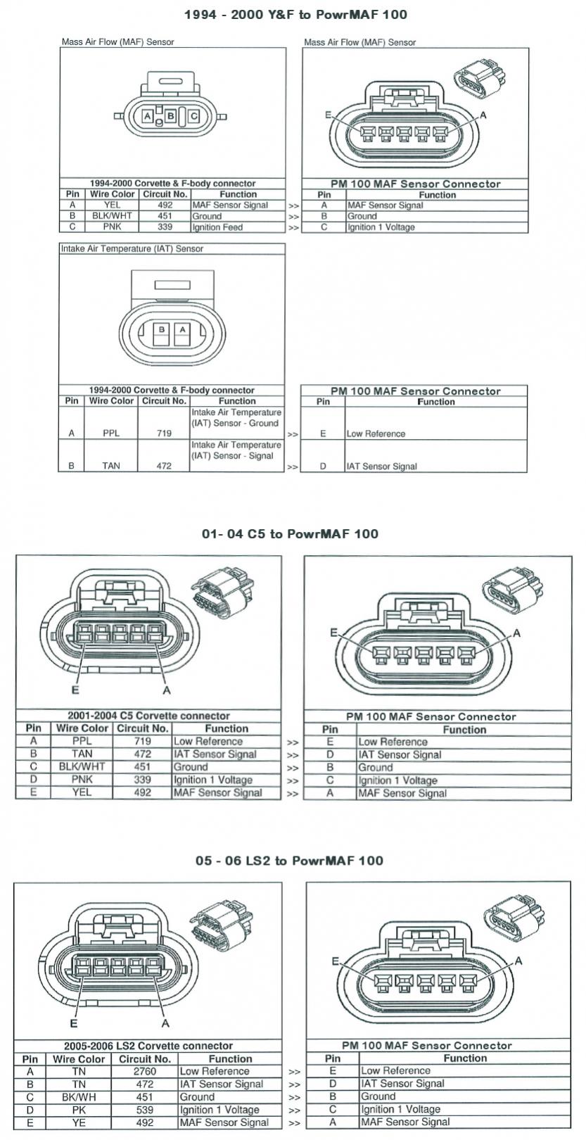
LG_7570 2013 Ford Map Sensor Wiring Diagram Schematic Wiring from static-cdn.imageservice.cloud Pin outs for an ls2 maf sensor. The easiest is to buy the adapter wiring harness and ls1 calibrated maf from pace parts. I am building a factory five gtm, using an ls2 crate engine, and a gmpp ls2 controller kit with e67 ecm. New pigtail assembly to repair the mass air flow sensor connector for the listed applications. Maf sensor wiring diagram wiring diagram maf sensor wiring diagram please organisedmum de. I also show you how you can figure out the wires without a wiring diagram. E 0.35 tn 472 intake air temperature sensor signal. Ho2s low signal bank 2 sensor 2:
Here is a video on how you can test your maf sensor using a basic $5 multimeter.
3 wire to 5 wire ls3 blade style maf harness adapter. Each component should be placed and linked to different parts in particular manner. The first ls1 maf sensor (top left) was introduced in 1994 for use with the lt1 engine. Maf sensor wiring diagram wiring diagram maf sensor wiring diagram please organisedmum de. For lt1, ls1, lt4, and many other gm 3 wire maf applications. Here is a video on how you can test your maf sensor using a basic $5 multimeter. One feature that makes all ls engines popular for project cars is the interchangeability of the different parts. In this instance, it will be a black wire, that will go to a ground splice. E 0.35 tn 472 intake air temperature sensor signal. The adapter kit offered by wiring specialties allows the oem s13/14 coolant temp sensor to thread into the rear passenger head, and the oem s13/14 oil pressure sensor into the block in the factory gm oil sensor location. Electric drill 1 5/8 hole saw note: The 5 wire ls1 maf wiring diagram works out to these five values: I eliminated those as the cause for the cel light after doing some research.
May 31, 2021 in addition to wiring harnesses, psi carries holley products, vintage air a/c, dakota digital gauges, hptuners and pcm programming, fuel pump kits. Ls1 3 wire coolant temperature temp sensor wiring connector 97 98 gm corvette see more like this. The controller kit came with the standard cartridge type maf sensor that is mounted in. Ho2s low signal bank 2 sensor 1: If the wires are okay, replace mass.
Ls1 Maf Sensor Wiring Diagram - Wiring Diagram Schemas from www.ls1gto.com The nissan oil and coolant sensors can be found on your nissan engine. Any wire not highlighted does not get touched, its required for proper engine/transmission control. If not, the structure won't work as it ought to be. Ls1 3 wire coolant temperature temp sensor wiring connector 97 98 gm corvette see more like this. If requirements are for 4 oxygen sensors, evap system, then you will not want to remove those components. The air temperature sensor (iat / ats) connector uses the standard delphi. B 0.8 bk/wh 451 ground. May 31, 2021 in addition to wiring harnesses, psi carries holley products, vintage air a/c, dakota digital gauges, hptuners and pcm programming, fuel pump kits.
The controller kit came with the standard cartridge type maf sensor that is mounted in.
Found this, just want to match everything up. Ls1 3 wire coolant temperature temp sensor wiring connector 97 98 gm corvette see more like this. A yel 492 mass air flow (maf) sensor signal b blk/wht 451 ground c pnk 539 ignition feed. The air temperature sensor (iat / ats) connector uses the standard delphi. A 0.35 ye 492 mass air flow (maf) sensor signal. Ls1 maf wiring diagram / mafless tuning wikipedia : May 31, 2021 in addition to wiring harnesses, psi carries holley products, vintage air a/c, dakota digital gauges, hptuners and pcm programming, fuel pump kits. 5 4.1.2 if you are going to use a 4l60e transmission, tape off and store the skip shift light wire, skip shift solenoid and reverse lockout solenoid connectors. B 0.8 bk/wh 451 ground. Related searches for ls1 maf sensor wiring diagram ls1 maf sensorls1. In this instance, it will be a black wire, that will go to a ground splice. I recently picked up a 97 lt1 it gave me to codes which were 0100 which is the maf and 1657 which is the skip shift solenoid. D 0.35 tn 2760 low reference.
The instructions say to use 4 inch diameter intake, and to weld the mounting boss to the intake such that it is in the center of a straight run of at least 6 inches, at least 10 inches away from the throttle body. The 5 wire ls1 maf wiring diagram works out to these five values: Each component should be placed and linked to different parts in particular manner. For lt1, ls1, lt4, and many other gm 3 wire maf applications. This is probably the more proper way to do this modification, however reprogramming is expensive and daunting to most people.
does anyone have the wiring diagram for the 3 and 5 wire maff - LS1TECH - Camaro and Firebird ... from ls1tech.com New pigtail assembly to repair the mass air flow sensor connector for the listed applications. I am building a factory five gtm, using an ls2 crate engine, and a gmpp ls2 controller kit with e67 ecm. Ls1 cam sensor wiring diagram diagram data schema. You must use the vehicle speed sensor (vss), correct brake switch and a gear indicator switch. In this instance, it will be a black wire, that will go to a ground splice. Any wire not highlighted does not get touched, its required for proper engine/transmission control. The 5 wire ls1 maf wiring diagram works out to these five values: The air temperature sensor (iat / ats) connector uses the standard delphi.
Pin outs for an ls2 maf sensor.
I also show you how you can figure out the wires without a wiring diagram. It is possible to use any mass airflow sensor on any engine, however the pcm needs programmed with the correct maf calibration data. A yel 492 mass air flow (maf) sensor signal b blk/wht 451 ground c pnk 539 ignition feed. The 5 wire ls1 maf wiring diagram works out to these five values: Pin outs for an ls2 maf sensor. Pin a maf output is the main pin you'll want to test for maf errors. Ls1 3 wire coolant temperature temp sensor wiring connector 97 98 gm corvette see more like this. It shows the components of the circuit as simplified shapes, and the facility and signal links together with the devices. I found that the o2 sensors as well as the maf and skip shift were all. I am building a factory five gtm, using an ls2 crate engine, and a gmpp ls2 controller kit with e67 ecm. Found this, just want to match everything up. This plug and play maf adapter extension harness can also be used to extend and plug and play extension harness can be used with 5 wire ls1, ls6, ls2. Each component should be placed and linked to different parts in particular manner.